
Timber drying stress detection device and method

A wood drying and detection device technology, which is applied in the direction of wood testing, material inspection products, etc., can solve the problems that the layered slicing method cannot be directly measured continuously in a timely manner, and the test accuracy is difficult to be guaranteed, and achieves the effect of simple structure and easy installation

Inactive Publication Date: 2008-03-26
NORTHEAST FORESTRY UNIVERSITY
View PDF0 Cites 10 Cited by
  • Summary
  • Abstract
  • Description
  • Claims
  • Application Information

AI Technical Summary

Problems solved by technology

[0005] The purpose of the present invention is to provide a stress detection device and method in the drying process of wood, which can solve the problem that methods such as layered slicing method, comb tooth method and tile bending method cannot be directly and timely measured continuously, and cannot be quantified directly. It is difficult to guarantee the test and test accuracy

Method used


Image

  • Timber drying stress detection device and method
  • Timber drying stress detection device and method
  • Timber drying stress detection device and method

Examples


specific Embodiment approach 1

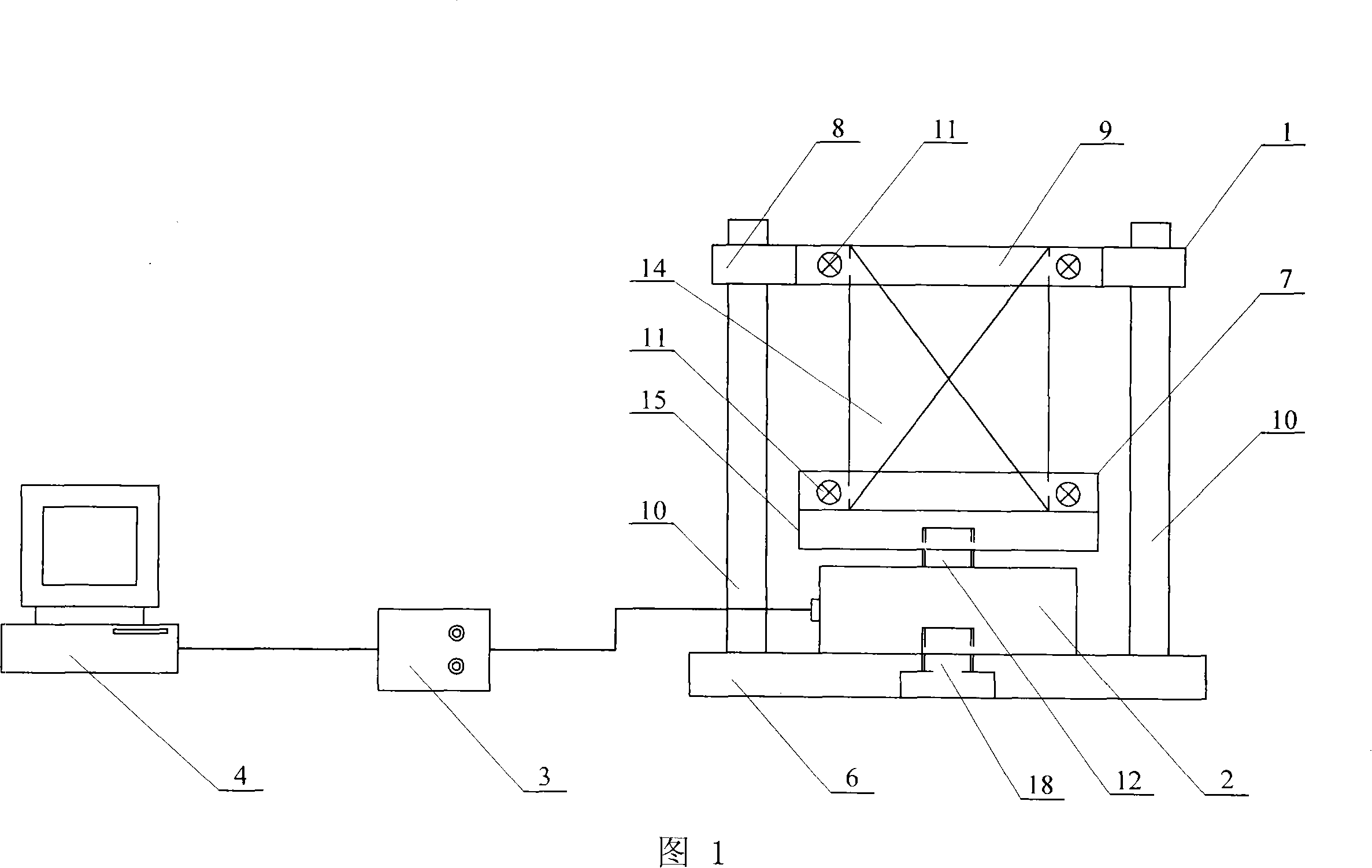
[0009] Embodiment 1: This embodiment is described in conjunction with FIG. 1 . The device of this embodiment is composed of a clamp 1, a tensile stress sensor 2, an analog-to-digital converter 3, and a computer 4; the tensile stress sensor 2 is fixed on the clamp 1 Above, the output end of the tensile stress sensor 2 is connected to the input end of the analog-to-digital converter 3 , and the output end of the analog-to-digital converter 3 is connected to the input end of the computer 4 . The model of the tensile stress sensor 2 in this embodiment is TLP-2KNHS, manufactured by Tokyo Shoki Research Institute, Japan; the model of the analog-to-digital converter 3 is DC-104R, manufactured by Tokyo Sekki Research Institute of Japan.

specific Embodiment approach 2

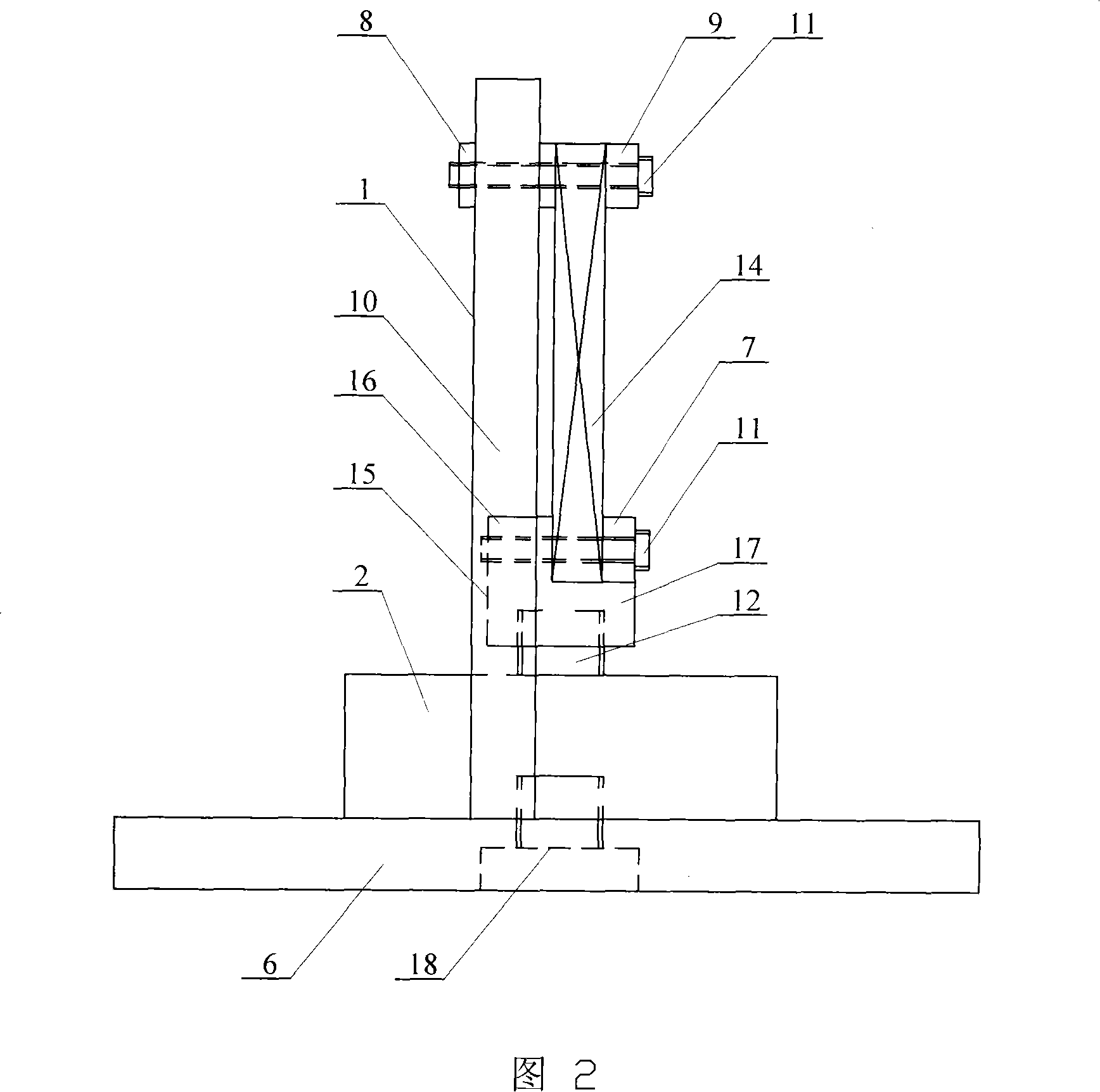
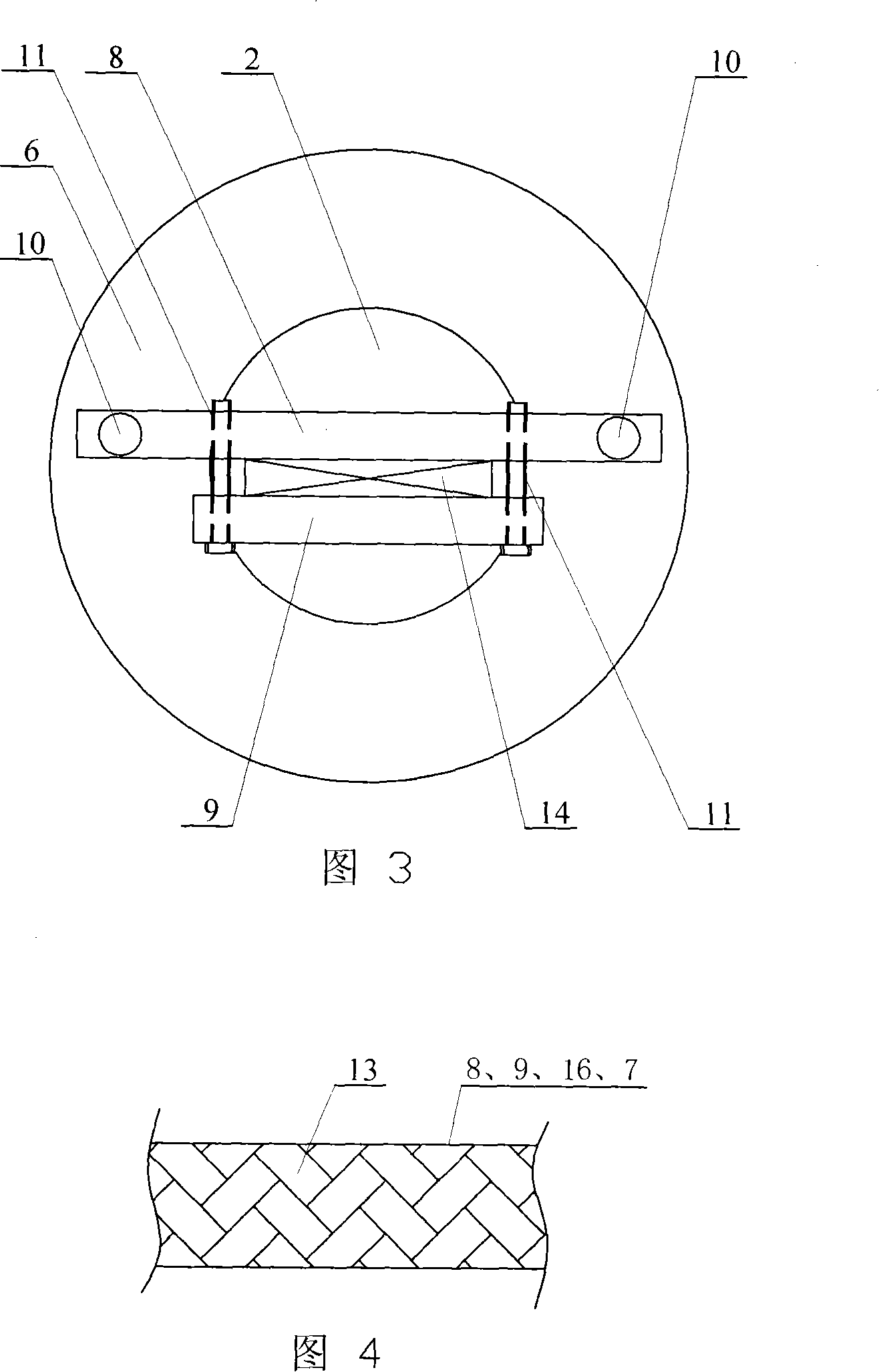
[0010] Specific Embodiment 2: This embodiment is described in conjunction with FIGS. 1 to 3. The fixture 1 of this embodiment consists of a long upper fixture plate 8, a short upper fixture plate 9, a short lower fixture plate 7, an L-shaped lower fixture plate 15, two A pillar 10, four bolts 11, a base 6 and connecting bolts 18 are formed; the two pillars 10 are fixed on the base 6 in parallel in the vertical direction, and the upper ends of the two pillars 10 are connected to the two ends of the long upper fixture plate 8 Fixed connection, the short upper jig plate 9 is located directly in front of the long upper jig plate 8, the vertical plate 16 of the L-shaped lower jig plate 15 is located below the long upper jig plate 8, and the short lower jig plate 7 is located on the short upper jig plate Just below the plate 9, and the short lower fixture plate 7 is installed on the horizontal plate 17 of the L-shaped lower fixture plate 15, between the two ends of the short upper fi...

specific Embodiment approach 3

[0011] Specific embodiment three: This embodiment is described in conjunction with Fig. 2 and Fig. 4, the inner side of the long upper jig plate 8 and the short upper jig plate 9 of this embodiment, and the vertical plate 16 of the L-shaped lower jig plate 15 and the short lower jig plate. Knurls 13 are respectively provided on the corresponding inner surfaces between the clamping plates 7 . Such setting can increase the frictional force between the clamp 1 and the wood test piece 14 to ensure that the wood test piece 14 is firmly clamped on the clamp 1 . Other components and connections are the same as those in the second embodiment.


PUM


Abstract

Stress detection equipment and method in wood dryness process. It relates to a kind of wood detection equipment and method. Aim to the problem that the laminar section-cutting method, the hackle method, the tile bend method can not detect directly and continuously, and it can not fix quantify test directly, its test accuracy is hard to assure. The instrument is: the tension stress sensor is fixed in the clamp, the tension stress sensor links with the modules convertor, the modules convertor links with the computer; the method is: fixes the wood sample in the clamp and dries it, when the wood sample shrinks and distorts, it produces shrink stress because of being restrained, and inputs it in the modules convertor to convert into digital signals through the analog signals of the tension stress sensor, then inputs in the computer test the stress in the dry process of the wood sample updating and continuously. Using the instrument and method in this invention can test the shrink stress in the dry process of the wood directly, updating and continuously.

Description

technical field [0001] The invention relates to a wood detection device and method. Background technique [0002] Wood drying stress is the main parameter and basis for researching and formulating wood drying process benchmarks. However, due to the variability and complexity of wood itself, it has brought many difficulties and inconveniences to the testing of wood drying stress. So far, how to quickly and accurately Testing wood drying stress is still a big problem for wood scientists. In the 1950s, Mc.Millen first proposed a method for measuring the drying stress of wood - the layered slice method. Tooth profile method, for qualitative research on drying stress, is mainly used in drying practice. In 1972, Shigeru Nishio proposed a method for determining the drying stress of wood by the tile bending method. In the past two decades, with the introduction of some new testing instruments and technologies into the field of wood drying research, some new wood drying stress tes...

Claims


Application Information

Patent Timeline
Patent Type & Authority Applications(China)
IPC IPC(8): G01N33/46
Inventor 程万里師岡敏朗刘一星韩广萍
Owner NORTHEAST FORESTRY UNIVERSITY
Learn More