A method, device and system for bandwidth allocation

A bandwidth and unified technology, applied in the field of network communication, can solve problems such as inability to meet data transmission requirements and waste of resources

Inactive Publication Date: 2008-03-26
NEW H3C TECH CO LTD
View PDF0 Cites 8 Cited by
  • Summary
  • Abstract
  • Description
  • Claims
  • Application Information

AI Technical Summary

Problems solved by technology

[0005] In actual service implementation, the uplink data traffic of each CNU is usually different. For example, CNU1 needs to occupy 4ms uplink bandwidth for Internet service and IP phone service at the same time, while CNU2 only needs to take up 2ms for Internet service. Uplink bandwidth. In this way,

Method used


Image

  • A method, device and system for bandwidth allocation
  • A method, device and system for bandwidth allocation
  • A method, device and system for bandwidth allocation

Examples


Embodiment Construction

[0030] In order to make the objectives, technical solutions and advantages of the present invention clearer, the present invention will be further described in detail below in conjunction with the accompanying drawings and specific embodiments.

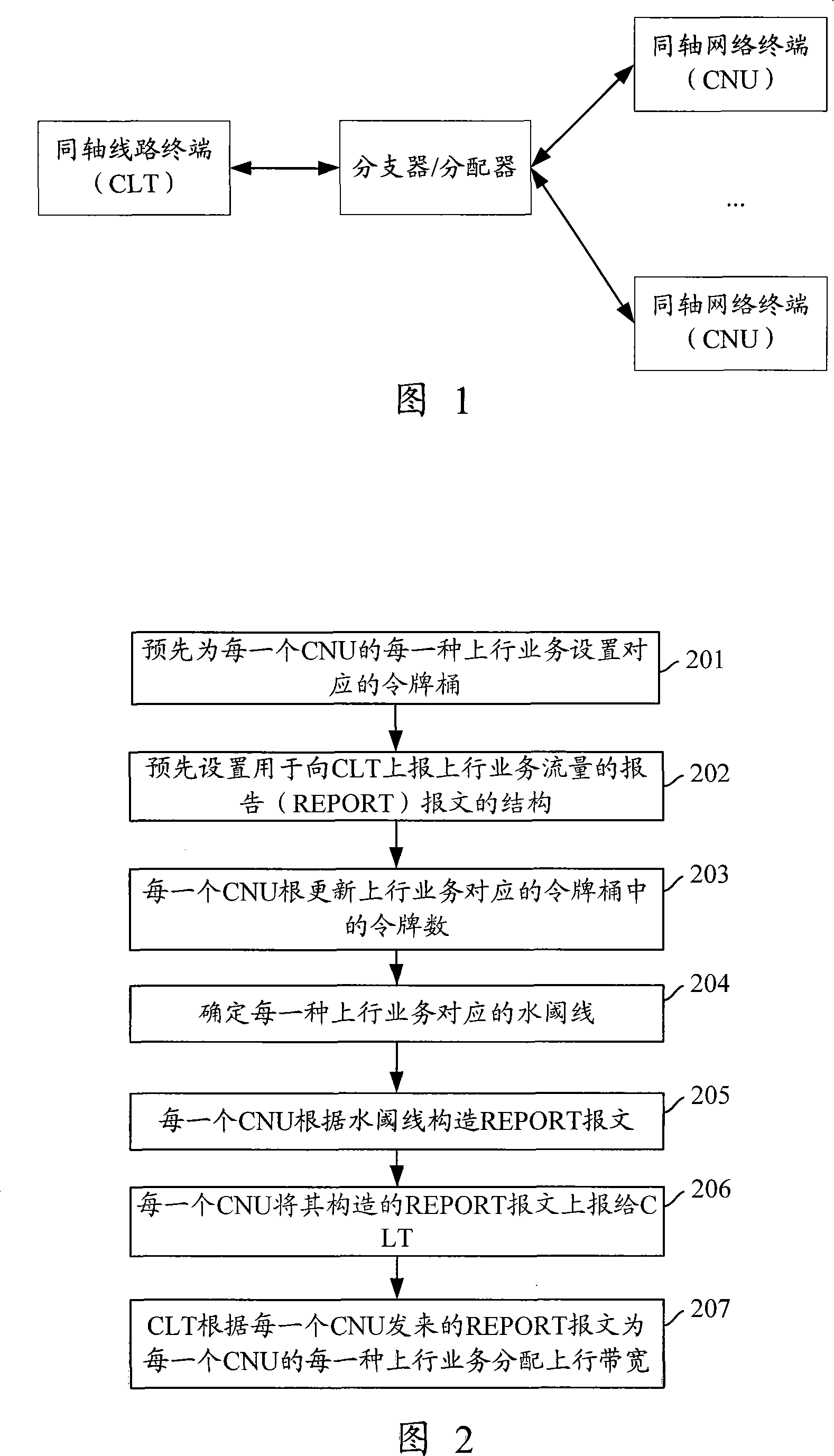
[0031] In order to dynamically allocate uplink bandwidth to each CNU according to the upstream data traffic of each CNU and maximize the utilization of the upstream bandwidth, each CNU must periodically report its own upstream data flow information to the CLT. In this way, the CLT knows each After the upstream data flow information of the CNU, the upstream bandwidth suitable for each CNU in the next upstream transmission cycle can be allocated.

[0032] In addition, in actual service implementation, users usually require different uplink services on the CNU to have different service levels. For this reason, it is necessary to set the corresponding Service Level Agreement (SLA) parameters for each different uplink service on the CNU. Throu...


PUM


Abstract

The invention discloses a method for bandwidth allocation, which includes the following steps: a token bucket corresponding to every uplink service set for each CNU of an Ethernet over Coax is arranged; during the period of uplink transmission, each CNU renews the numbers of the tokens in the bucket according to the corresponding parameter of the Service Level Agreement (SLA) of every uplink service, then, a REPORT message carrying the information of uplink service traffic flow is formed according to the number of the tokens in the bucket corresponding to the uplink service, and the report is transmitted to the CLT of Ethernet over Coax; according to the REPORT message of each CNU, the CLT distributes the uplink bandwidth for each CNU. The invention also discloses a system for CNU, CLT and distribution. The invention ensures an appropriate allocation of uplink bandwidth to every CNU, thus improving the utilization rate of the uplink bandwidth.

Description

Technical field [0001] The present invention relates to network communication technology, in particular to a method, equipment and system for allocating bandwidth. Background technique [0002] At present, based on the network structure of the Ethernet Passive Optical Network (EPON), an Ethernet Passive Coaxial-cable Network (EPCN) system has emerged. The EPCN system uses Ethernet as the carrier, adopts a point-to-multipoint structure and a passive coaxial cable transmission method, and sends data streams in bursts of Ethernet packets in the upstream. Figure 1 is a schematic diagram of the structure of the EPCN system. As shown in Figure 1, the EPCN system mainly includes a coaxial cable carrying Ethernet head end (CLT, Coaxial-cable Line Terminal), splitter / distributor, and multiple coaxial cable carrying Ethernet terminal (CNU, Coaxial-Cable Network Unit). The EPCN system connects various Ethernet devices through CLT, and connects user equipment through CNU. The EPCN system is ...

Claims


Application Information

Patent Timeline
IPC IPC(8): H04L12/56H04L12/28H04L12/911
Inventor 文闻
Owner NEW H3C TECH CO LTD
Why Eureka
Try Eureka