Flat video display device

An image display, flat-panel technology, applied in the direction of instruments, static electricity, electrical components, etc., can solve the problems of increasing labor costs, prolonging the overall operation process, etc., to achieve the effect of enhancing strength and stable support

Inactive Publication Date: 2008-03-26
NANJING LG TONGCHUANG COLOR DISPLAYS SYST CO LTD
0 Cites 3 Cited by

AI-Extracted Technical Summary

Problems solved by technology

[0019] Therefore, in order to install the above-mentioned grounding wire, it is necessary to separately perform soldering w...

Method used

Above-mentioned front panel 110 is connected in the display module 21 (referring to Fig. 1) front portion that is used for displaying image, is responsible for supporting display module 21; Above-mentioned decorative plate 120 is arranged on the lower side of front panel 110, and it can raise flat plate The visual aesthetics of the type image ...

Abstract

The invention provides a flat type image display device which can not need use other earth wires to prevent statical electricity generating, also can increase the strength of the front panel for supporting the display. The flat type image display device comprises: the front panel which is connected with the front of the display for displaying images; a resin decorating plate which is arranged under the front panel, the central position thereof is provided with a subtransparent indicating window which can be permeated by light; a pair of metal frames which are arranged correspondingly on the upper and lower ends of the decorating plate; a metal material supporting frame which is combined with the metal frame and provided with an opening part communicated with the indicating window; a printed circuit board which is combined with the supporting frame and displays channel information on the indicating window.

Application Domain

Instrument housingElectrical apparatus contructional details +2

Technology Topic

ElectricityPrinted circuit board +6

Image

  • Flat video display device
  • Flat video display device

Examples

  • Experimental program(1)

Example Embodiment

[0037] Hereinafter, preferred embodiments of the present invention that can achieve the above objects will be described with reference to the accompanying drawings. In the description of this embodiment, the same structure uses the same name and the same symbol, and additional description of the structure will be omitted later.
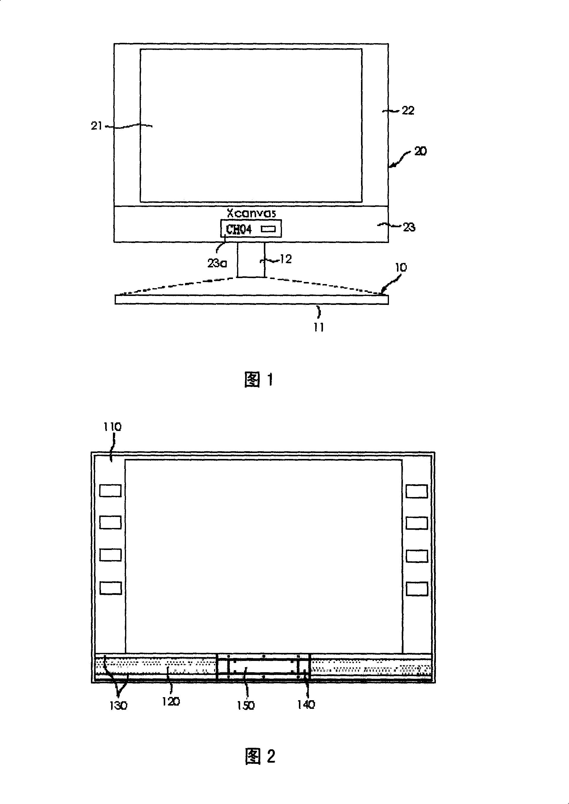
[0038] Fig. 2 is a schematic diagram of a state where a support frame and a printed circuit board are connected to the front panel based on the present invention.
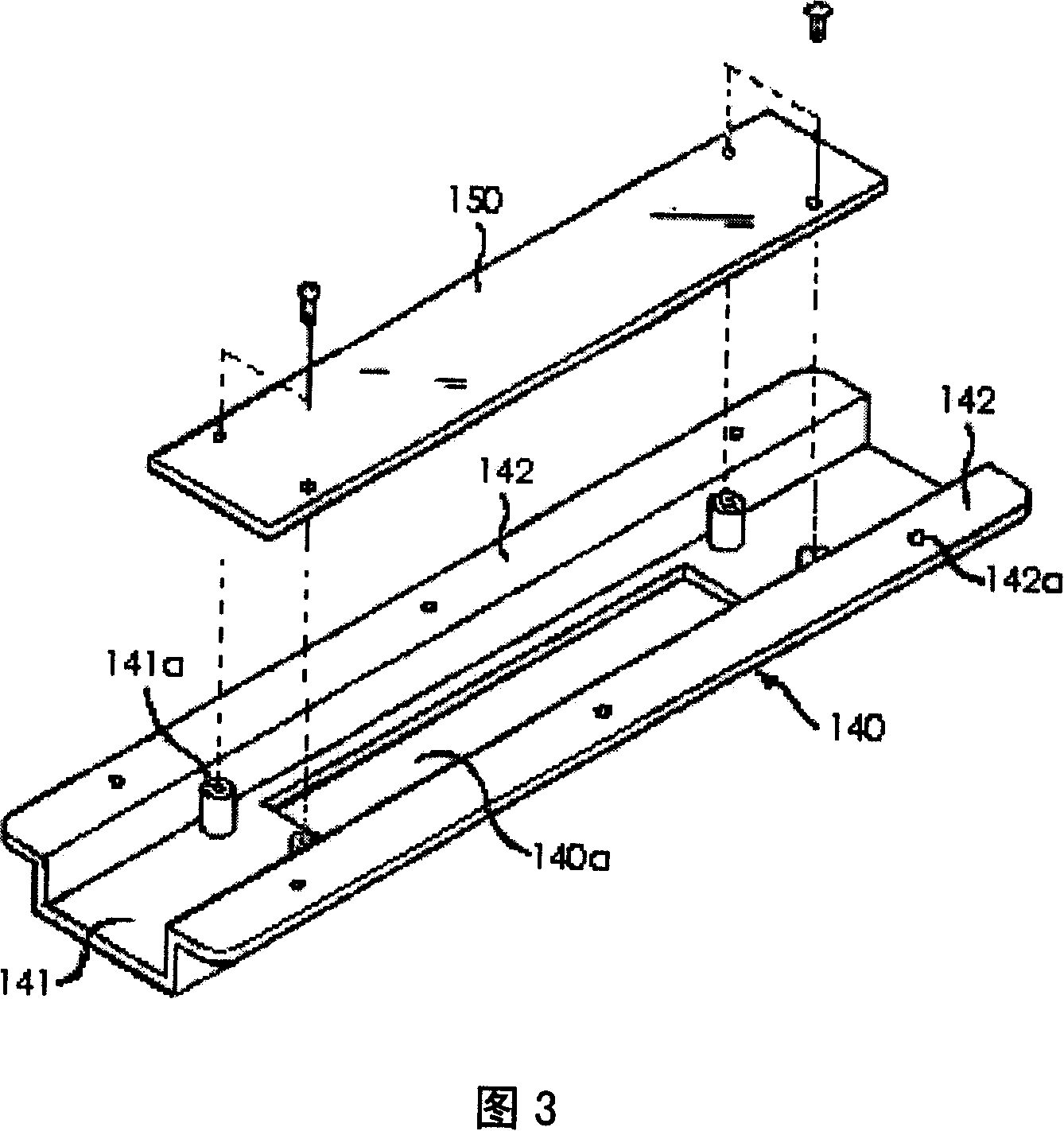
[0039] 2, the flat-panel image display device based on the present invention is composed of a front panel 110, a decorative board 120, a metal frame 130, a support frame 140 and a printed circuit board 150.
[0040] The front panel 110 is connected to the front of the display module 21 (refer to FIG. 1) for displaying images, and is responsible for supporting the display module 21; the decorative board 120 is provided on the lower side of the front panel 110, which can improve the flat-panel image display The visual beauty of the installation.
[0041] Here, the above-mentioned decorative board 120 is made of a resin-based translucent material, and an indicator window 23a (refer to FIG. 1) is provided in the middle. At this time, the above-mentioned decorative board 120 paints all parts other than the indicating window 23a in black. Therefore, only the indicator window 23a maintains a translucent state capable of passing light.
[0042] The metal frames 130 are provided at the upper and lower ends of the decorative board 120 in pairs corresponding to each other. Such a metal frame 130 can increase the strength of the resin decorative board 120, so that the front panel 110 can support the display module 21 more stably.
[0043] The support frame 140 is made of a metal material, its upper and lower ends are connected to the metal frame 130, and an opening 140a communicating with the indicator window 23a is provided in the center (refer to FIG. 3).
[0044] Such a support frame 140 can increase the strength of the front panel 110 made of resin material like the metal frame 130 described above, so as to support the display module 21 more stably.
[0045] The printed circuit board 150 is connected to the support frame 140, and can display information such as channels on the indicator window 23a by light emission.
[0046] To this end, the printed circuit board 150 is provided with a plurality of light emitting diodes (not shown) that can emit light as long as the power is turned on, and the light emitting diodes display necessary information under the control of the printed circuit board 150.
[0047] At this time, the information displayed by the light-emitting diodes is displayed on the translucent indicator window 23a through the opening portion 140a. In this way, the user can visually confirm various information through the indicator window 23a.
[0048] The structure of the aforementioned support frame 140 will be described in more detail below.
[0049] Fig. 3 is an exploded perspective view of the combined structure of the support frame and the printed circuit board based on the present invention.
[0050]Referring to FIG. 3, the supporting frame 140 is generally composed of a main board 141 and a pair of connecting pieces 142.
[0051] The printed circuit board 150 is connected to the main board 141, and an opening 140a is provided in the center thereof. In addition, the main board 141 is provided with an internally threaded nut post 141a for connecting the printed circuit board 150 and the bolt.
[0052] In addition, the pair of connecting pieces 142 is screwed to the metal frame 130 (refer to FIG. 2) provided on both sides of the main board 141. To this end, the connecting piece 142 is provided with a plurality of bolt holes 142a. Of course, the metal frame 130 is also provided with bolt holes (not shown) corresponding to the bolt holes 142a.
[0053] Similarly, the main board 141 of the supporting frame 140 is connected to the printed circuit board 150 by screws, and the connecting piece 142 of the supporting frame 140 is connected to the metal frame 130 by screws.
[0054] Therefore, if the support frame 140 and the metal frame 130, the printed circuit board 150 and the support frame 140 are respectively connected, the printed circuit board 150 can be electrically connected to the metal frame 130 through bolts.
[0055] As a result, if the printed circuit board 150 is connected to the above-mentioned support frame 140, the printed circuit board 150 will naturally realize the grounding state connected to the metal frame 130.
[0056] Of course, the connection between the support frame 140 and the metal frame 130, the printed circuit board 150 and the support frame 140 is not only achieved by screws, but can be achieved by various connecting tools such as hooks.
[0057] Through the above description, the relevant staff can make various changes and modifications within the scope of the technical idea of ​​the present invention. Therefore, the technical scope of the present invention is not limited to the content of the specification, and its technical scope must be determined according to the scope of the claims.

PUM

no PUM

Description & Claims & Application Information

We can also present the details of the Description, Claims and Application information to help users get a comprehensive understanding of the technical details of the patent, such as background art, summary of invention, brief description of drawings, description of embodiments, and other original content. On the other hand, users can also determine the specific scope of protection of the technology through the list of claims; as well as understand the changes in the life cycle of the technology with the presentation of the patent timeline. Login to view more.

Similar technology patents

Protective sheet for solar battery module, method of fabricating the same and solar battery module

InactiveUS7309831B2high strengthimprove in moistureproof property
Owner:DAI NIPPON PRINTING CO LTD

Humic acid long-acting compound fertilizer and its preparing method

InactiveCN1491924Ahigh strengthReduce broken rate
Owner:SHENYANG INST OF APPLIED ECOLOGY - CHINESE ACAD OF SCI

Classification and recommendation of technical efficacy words

  • high strength
  • stable support

Transformer station suspension bracket pedestal and spare transformer station suspension bracket

InactiveCN106517002Aeasy to movestable support
Owner:DONGMING POWER SUPPLY CO STATE GRID SHANDONG ELECTRIC POWER CO

Basal lamina determination device

InactiveCN1873373AEasy to supportstable support
Owner:SCREEN HLDG CO LTD

Drilling machine structure used for coal mine

ActiveCN106401468Astable supportFlexible drilling
Owner:HANGZHOU XIANGLONG DRILLING EQUIP TECH CO LTD

Arm support type camera support

PendingCN107859857AFlexible and quick focus and parameter adjustmentstable support
Owner:陈小鸣
Why Eureka
Try Eureka