Sound absorption structure body

A structure and frame technology, applied in sound insulation, railway car body, building components, etc., can solve the problems of increased thickness of sound-absorbing structures, limited indoor space, and large-scale sound-absorbing structures, reducing the number of parts and achieving high sound absorption. performance, the effect of improving the amount of sound absorption

Active Publication Date: 2008-03-26
GOERTEK INC
View PDF2 Cites 35 Cited by
  • Summary
  • Abstract
  • Description
  • Claims
  • Application Information

AI Technical Summary

Problems solved by technology

That is, in the sound-absorbing structure 100 shown in FIG. 17, it is necessary to enlarge the size of the sound-absorbing structure 110 itself.
In addition, in the sound absorbing structure 110 shown in FIG. 18, it is necessary to increase the thickness of the sound absorbing structure 110 itself.
[0018] When the resonance frequency f0 is lowered in this way, there is a problem that the size of the sound-absorbing structure itself increases or the thickness of the sound-absorbing structure itself increases.
Furthermore, when it is considered that the sound-absorbing structure is installed on, for example, the wall of a living room, there is a problem that the indoor space is limited as the sound-absorbing structure itself increases in size.
As a result, it is difficult for the conventional sound-absorbing structure to achieve both sound absorption in the low-frequency range and miniaturization of the sound-absorbing structure itself.

Method used


Image

  • Sound absorption structure body
  • Sound absorption structure body
  • Sound absorption structure body

Examples


no. 1 Embodiment approach

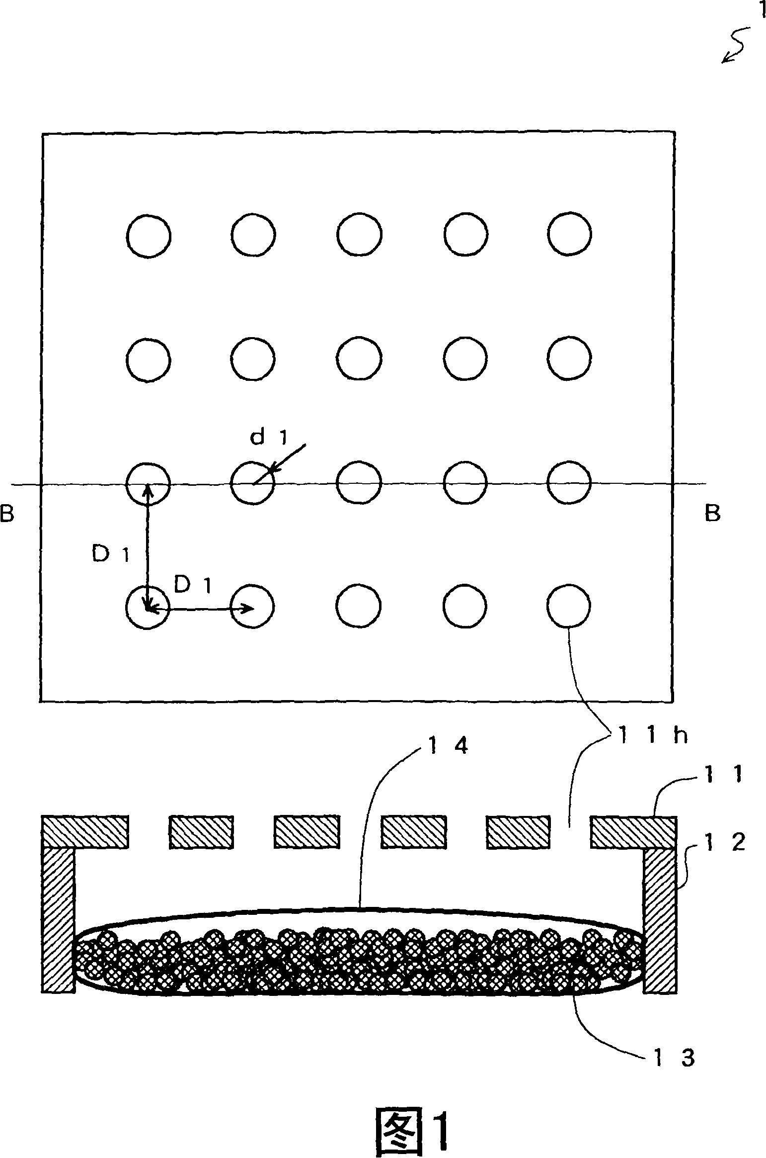
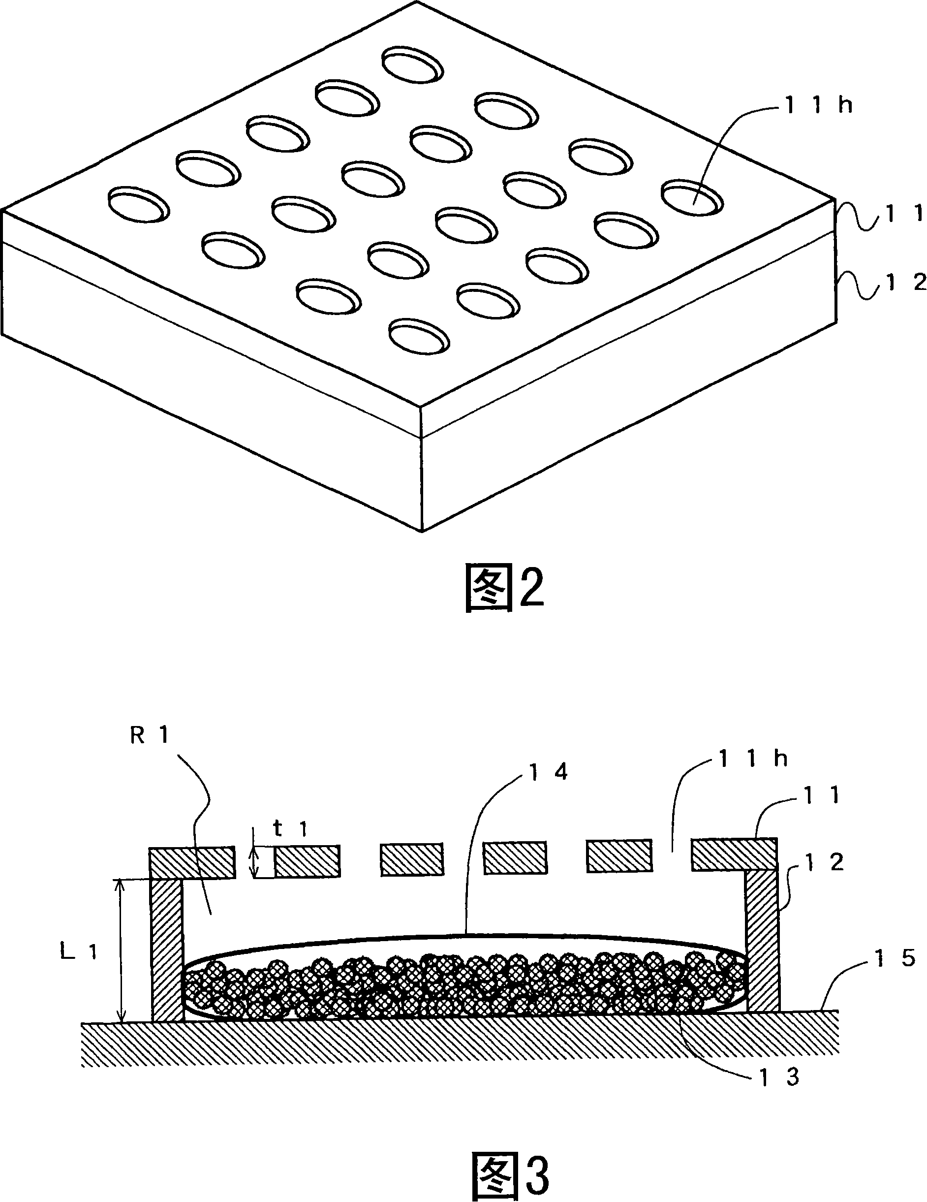
[0077] First, a sound-absorbing structure 1 according to a first embodiment of the present invention will be described with reference to FIGS. 1 to 3 . FIG. 1 is a diagram showing a front view of a sound absorbing structure 1 and a cross-sectional view taken along line B-B. FIG. 2 is a perspective view of the sound absorbing structure 1 . FIG. 3 is a structural cross-sectional view showing how the sound-absorbing structure 1 is installed on the wall 15 .

[0078] In FIG. 1 , a sound absorbing structure 1 includes a front panel 11 , a side panel 12 , a gas adsorbent 13 , and a shielding member 14 . The front panel 11 is a plate-shaped member such as a composite board, a hardboard such as gypsum, or metal. In FIG. 1, the front shape of the front panel 11 is a square as an example. A plurality of openings 11h are formed in the front panel 11 . The shape of the opening 11h is, for example, a circle or a slit shape. In FIG. 1, as an example, the positions of the openings 11h o...

no. 2 Embodiment approach

[0110] Next, a sound-absorbing structure 2 according to a second embodiment of the present invention will be described with reference to FIG. 12 . FIG. 12 is a cross-sectional view showing a structural example of the sound absorbing structure 2 . The sound absorbing structure 2 includes a front panel 21 , a side panel 22 , a rear panel 26 , an acoustic port 27 , a gas adsorbent 13 , and a shielding member 14 . In addition, the sound-absorbing structure 2 of this embodiment is different from the above-mentioned first embodiment in that only one opening is formed in the front panel 21 and that an acoustic port 27 is newly provided. Therefore, other than these parts are the same as those of the first embodiment, and description thereof will be omitted. Moreover, although the sound absorbing structure 2 is provided with the back panel 26 in this embodiment, the back panel 26 may be the wall 15 etc. as well. That is, the sound absorbing structure 2 can be constituted by the front...

no. 3 Embodiment approach

[0125] Next, a sound-absorbing structure 3 according to a third embodiment of the present invention will be described with reference to FIGS. 13 and 14 . FIG. 13 is a perspective view showing an example in which a sound absorbing structure 3 is configured as a sound absorbing structure 3 arranged around a noise source such as a road, a railway, or a factory. FIG. 14 is a structural sectional view of the sound absorbing structure 3 . The sound absorbing structure 3 includes a front panel 31, a side panel 32, a rear panel 36, a partition 37, a gas adsorbent 13, and a shielding member 14b. In addition, the sound-absorbing structure 3 of the present embodiment is significantly different from the above-mentioned first embodiment in the arrangement position of the gas adsorbent 13 . The gas adsorbent 13 and the shielding member 14b are the same as those of the above-mentioned first embodiment, and the same reference numerals are attached thereto, and description thereof will be omi...


PUM


Abstract

A sound absorption structure body has a housing has a front side and a side face raised at at least a part of an outer edge section of the front face, a gas adsorption body placed in the internal space, surrounded by the front face and the side face, of the housing and physically adsorbing gas in the internal space, a sealing means for sealing the gas adsorption body from the outside, and an acoustic connection section provided at at least either the front face or the side face and functioning as an acoustic mass for acoustically connecting the internal space of the housing and the space outside the housing. The sound absorption structure body achieves both sound absorption in a low -pitched sound range and downsizing of the sound absorption structure body itself.

Description

technical field [0001] The present invention relates to sound-absorbing structures, and more particularly to sound-absorbing structures that absorb noise. Background technique [0002] In recent years, the awareness of the living environment has been increasing, and the need to fully consider the sound environment such as noise from the outside is increasing. In this situation, anti-noise technology can be said to be a very important technology. As the most common noise prevention technology, a sound-absorbing structure 100 utilizing the Helmholtz resonance effect shown in FIG. 17 is known (for example, refer to Patent Document 1). FIG. 17 is a cross-sectional view of a conventional sound-absorbing structure 100 . The sound absorbing structure 100 includes an acoustic port 101 and a box 102 . An opening is formed on the front surface of the case 102, and the acoustic port 101 is fixedly installed. Here, it is assumed that the volume inside the box 102 is V0, the speed of...

Claims


Application Information

Patent Timeline
Patent Type & Authority Applications(China)
IPC IPC(8): E01F8/00B60R13/08B61D49/00E04B1/86G10K11/172
CPCB60R13/08B61D17/185G10K11/172E04B1/86E04B2001/8452E01F8/007E04B2001/8433E01F8/0011
Inventor 松村俊之佐伯周二
Owner GOERTEK INC
Why Eureka
Try Eureka