A ceramic armour element for use in armour
A technology of ceramics and components is applied in the field of armor panels providing anti-ballistic performance, which can solve the problems of falling off of tiles and adjacent tiles, destroying panels, and reducing the protective performance of panels, so as to improve the anti-ballistic performance and improve the level of protection. Effect
- Summary
- Abstract
- Description
- Claims
- Application Information
AI Technical Summary
Problems solved by technology
Method used
Image

Examples
Embodiment Construction
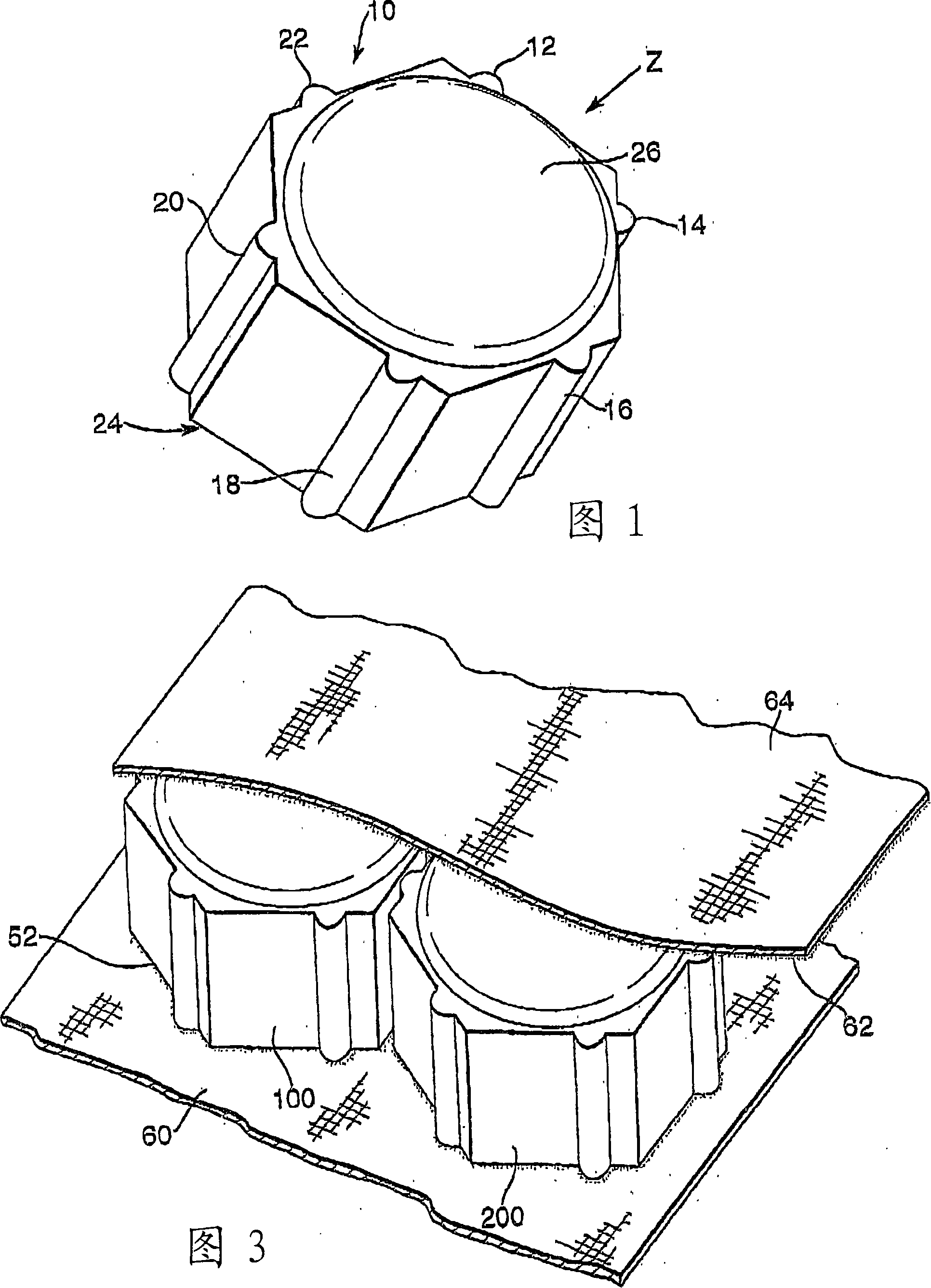
[0021] FIG. 1 shows a ceramic armor element 10 . When the ceramic armor element 10 is viewed in the direction indicated by Z, the ceramic armor element has a hexagonal cross-sectional shape. The ceramic armor element 10 has lugs 12 , 14 , 16 , 18 , 20 , 22 on each side of the ceramic armor element. The element has a flat lower surface 24 and a convex upper surface 26 . The convex upper surface serves to dissipate the energy from the initial impact of the projectile over a larger area than if the element had a flat upper surface.
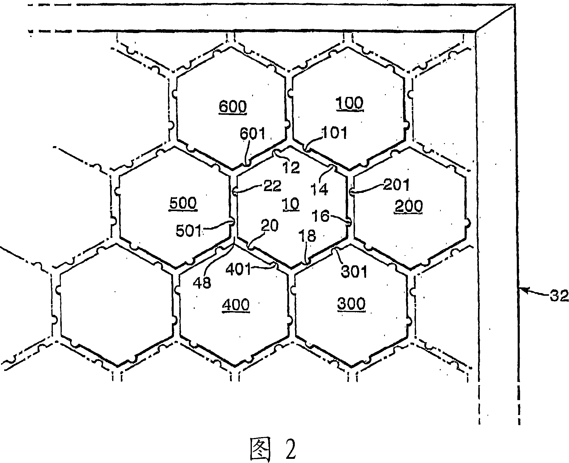
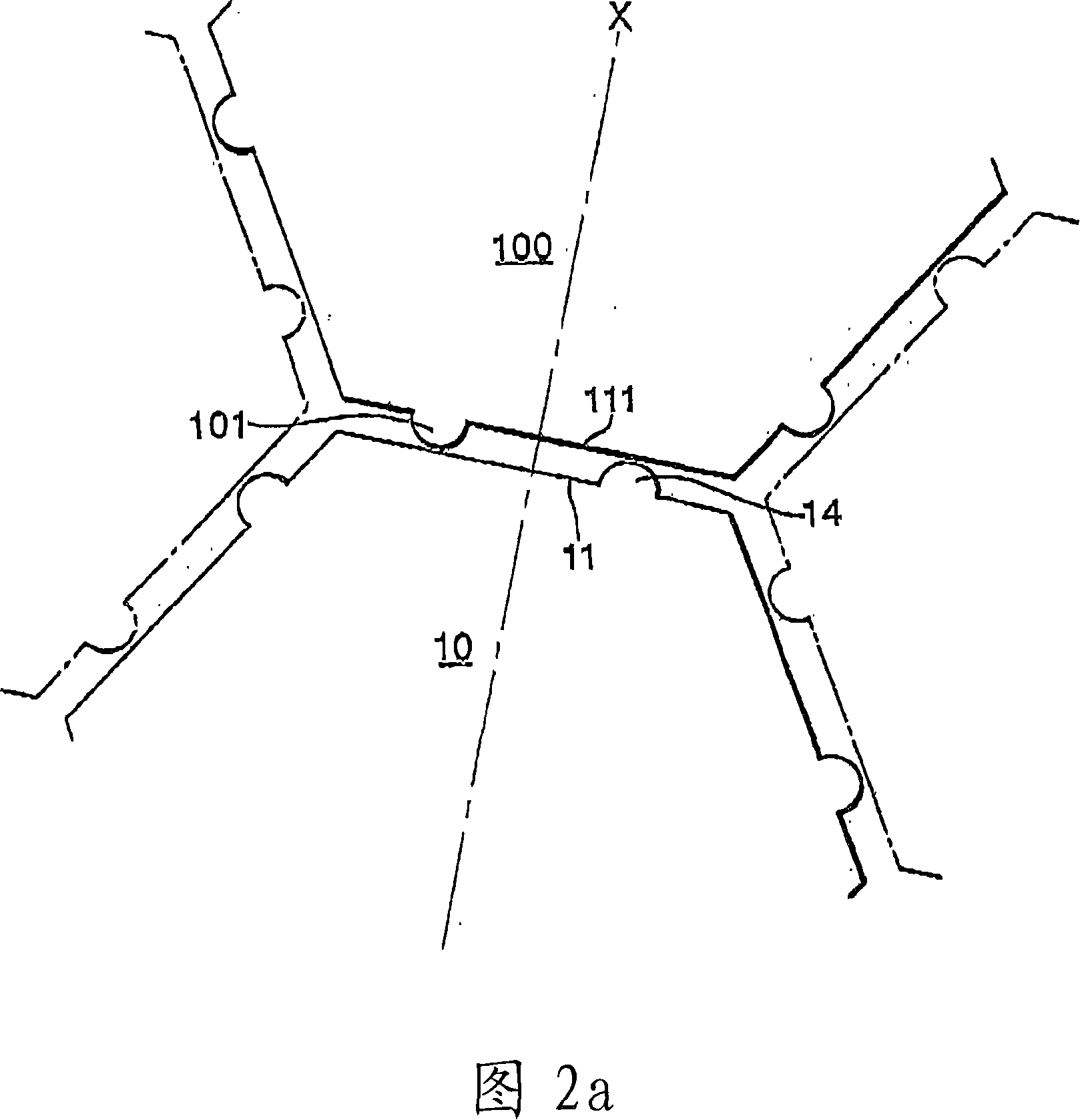
[0022] FIG. 2 shows an array of hexagonal ceramic armor elements comprising element 10 and identical elements 100 , 200 , 300 , 400 , 500 , 600 . The hexagonal array is arranged such that the lugs 12 , 14 , 16 , 18 , 20 , 22 on the ceramic armor element 10 cooperate with adjacent ceramic armor elements 100 , 200 , 300 , 400 , 500 , 600 . The lugs 101, 201, 301, 401, 501, 601 on the adjacent elements 100, 200, 300, 400, 500, 600 are arranged on the...
PUM
 Abstract
Description
Claims
Application Information