Evacuation apparatus

An evacuation device, gas technology, used in liquid variable volume machinery, liquid fuel engines, machines/engines, etc.

Inactive Publication Date: 2008-04-02
ANEST IWATA CORP
View PDF2 Cites 2 Cited by
  • Summary
  • Abstract
  • Description
  • Claims
  • Application Information

AI Technical Summary

Problems solved by technology

In Patent Document 2, there is no mention of increasing the pumping speed

Method used


Image

  • Evacuation apparatus
  • Evacuation apparatus
  • Evacuation apparatus

Examples


no. 2 example

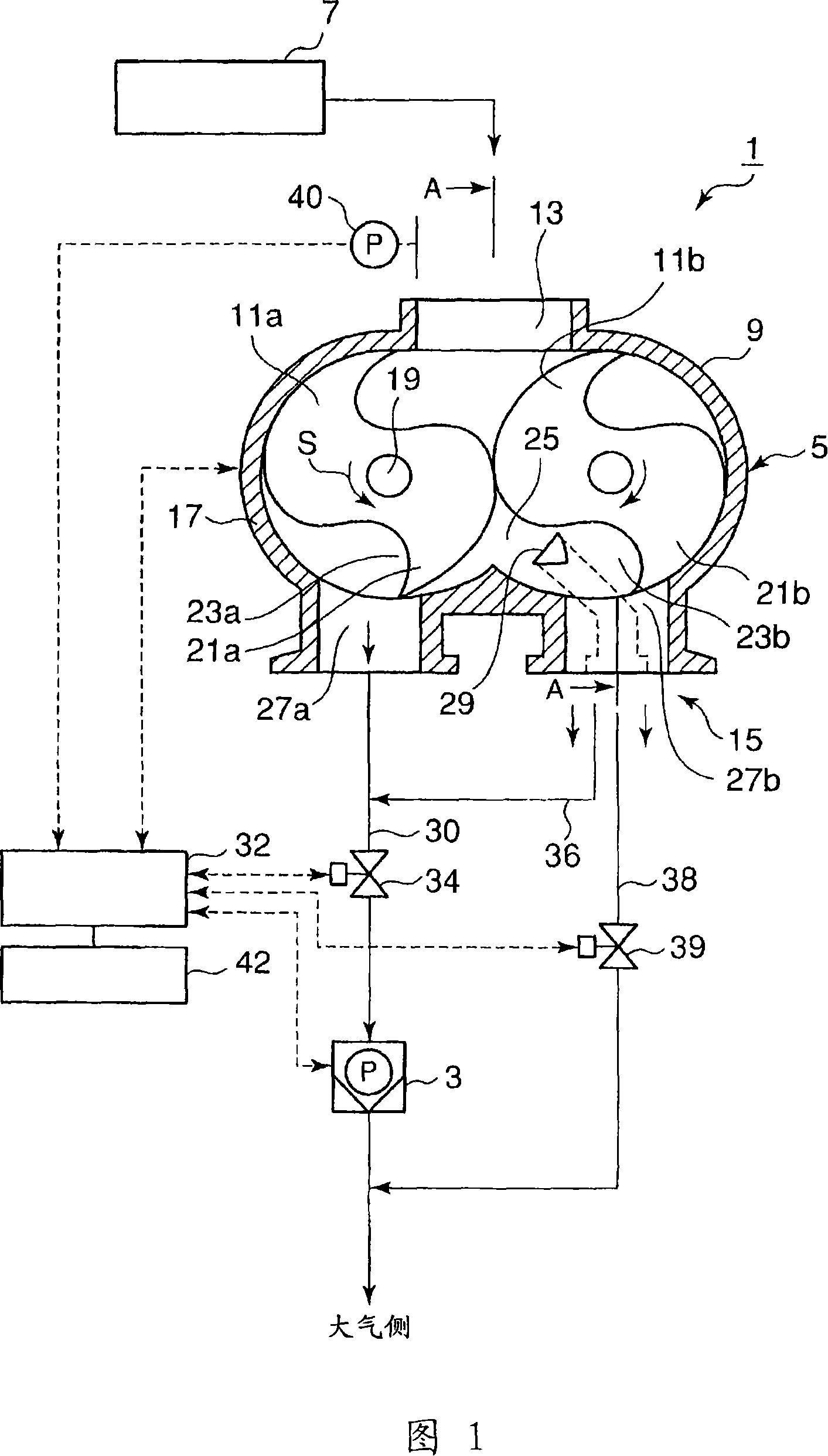
[0052] Then, a second embodiment will be described.

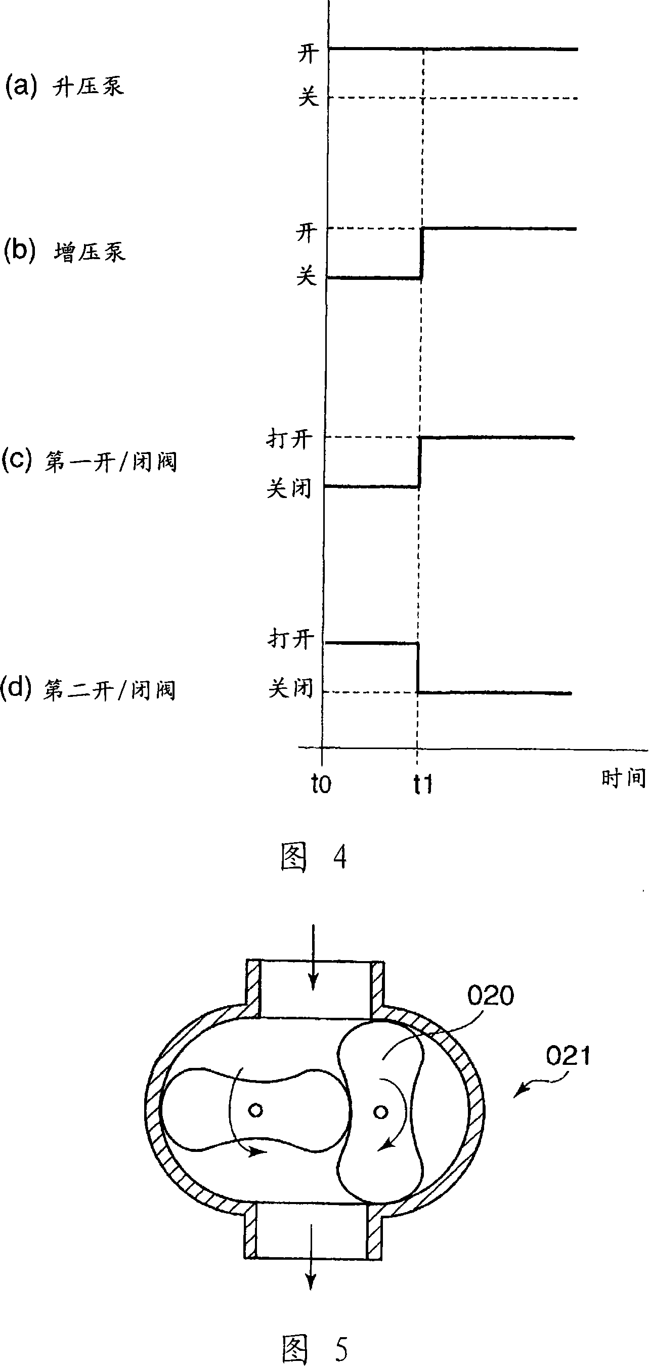
[0053] In this second embodiment, the elapsed time signal from the timer 42, rather than the pressure signal from the pressure sensor 40, switches the on / off state of the pumps 5 and 3, and also the on / off valve 34 and 39 on / off state conversion.

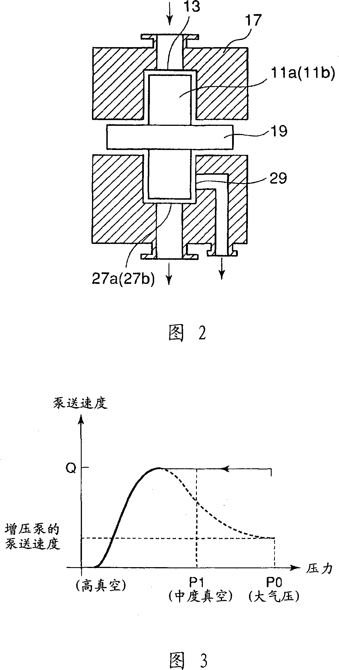
[0054] The time t1 is predetermined by calculation based on conditions such as the volume of the vacuum tank 7, the discharge capacity of the compression space 25 of the mechanical booster pump 5, specific operating factors of the mechanical booster pump 5, ambient temperature, etc. t1 is the time required for pressure P0 to drop to pressure P1 (medium vacuum).

[0055] When the controller recognizes that the time t1 has passed the time t0 through the signal from the timer 42, the controller controls the operating state so that the mechanical booster pump 5 is in the on state, the booster pump 3 is in the on state, and the first on The on / off valve 34 is in an open state, and t...


PUM


Abstract

The present invention proposes an evacuation apparatus including a mechanical booster pump 5 , a back pump 3 placed at a down-stream side of the mechanical booster pump in series, the booster pump 5 having discharge openings 27 a and 27 b for discharging a low compression gas and a discharge opening 29 for discharging a high compression gas, and, in a stage where gas-discharging is started, the gas is discharged toward the ambient side through the discharge opening 29 for discharging a high compression gas with the operation of the mechanical booster pump and, in a stage where the discharged gas pressure reaches afterward a medium vacuum, the back pump starts operation and the gas is sent to the back pump through the discharge openings 27 a and 27 b for discharging a low compression gas.

Description

technical field [0001] The present invention relates to an evacuation device for evacuating tanks, chambers and the like, provided with a mechanical vacuum booster pump and a booster pump arranged in series on the downstream side of the mechanical vacuum booster pump. Background technique [0002] In order to achieve vacuuming inside tanks, chambers, and the like at fast pumping speeds, conventionally, a pump for suction is used on the upstream side (vacuum side) of a vacuum pump (booster pump) with a relatively low pumping speed. Mechanical booster pump for vacuum. As for the mechanical booster pump, a Roots vacuum pump 021 is generally used, as shown in FIG. 5, which performs compression / exhaust work by rotating a pair of Roots vanes 020. And it is known that booster pumps can achieve several times the maximum pumping speed by using a mechanical booster pump. [0003] However, even though the mechanical booster pump sends a large amount of gas to the booster pump located...

Claims


Application Information

Patent Timeline
Patent Type & Authority Applications(China)
IPC IPC(8): F04B37/14F04B49/22F04C18/14F04C25/02B01J3/02H01L21/02
CPCF04C2220/12F04C28/06F04C28/02F04C25/02F04C18/126F04C23/005F04C2250/102
Inventor 谷川志郎
Owner ANEST IWATA CORP
Why Eureka
Try Eureka