Seal compressor

A technology of compressors and compression parts, which is applied in the direction of mechanical equipment, engine functions, engine components, etc., can solve the problems of cooling fan sound leakage, large guide parts, and large-scale packaged compressors, etc., to achieve noise reduction and noise suppression Effect

Inactive Publication Date: 2008-04-02
HITACHI LTD
View PDF2 Cites 15 Cited by
  • Summary
  • Abstract
  • Description
  • Claims
  • Application Information

AI Technical Summary

Problems solved by technology

[0012] However, in the packaged compressor disclosed in Patent Document 1, the cooling air inlet is arranged on the front surface, and the cooling fan is provided to face the inlet, so that the sound generated by the cooling fan directly leaks to the outside.
[0013] In addition, in the packaged compressor of Patent Document 2, different fans are used to cool the compressor main body and the engine, so the size of the packaged compressor is increased.
Furthermore, the packaged compr

Method used


Image

  • Seal compressor
  • Seal compressor
  • Seal compressor

Examples


Embodiment Construction

[0086] Hereinafter, a packaged compressor according to an embodiment of the present invention will be described in detail with reference to the drawings.

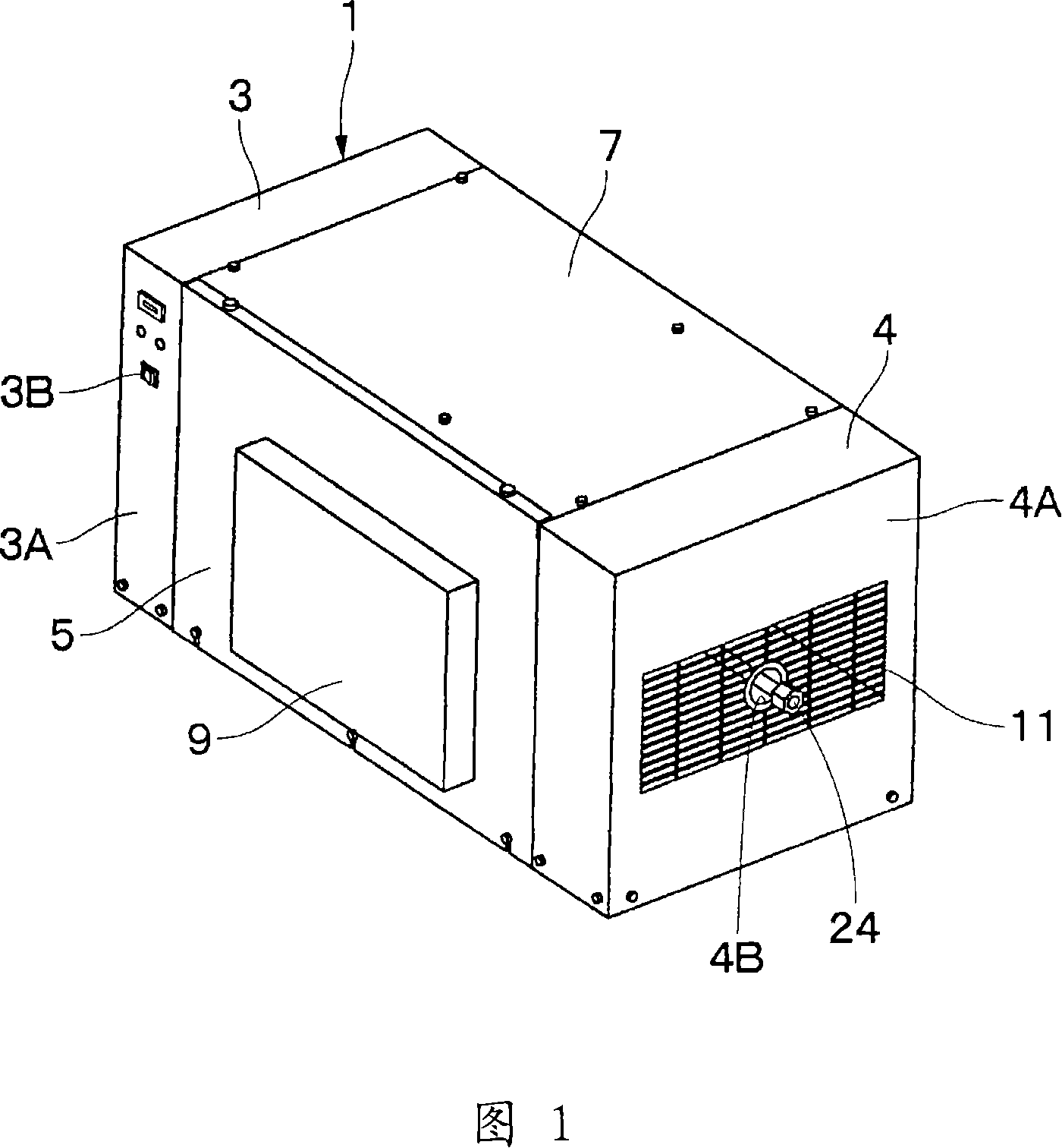
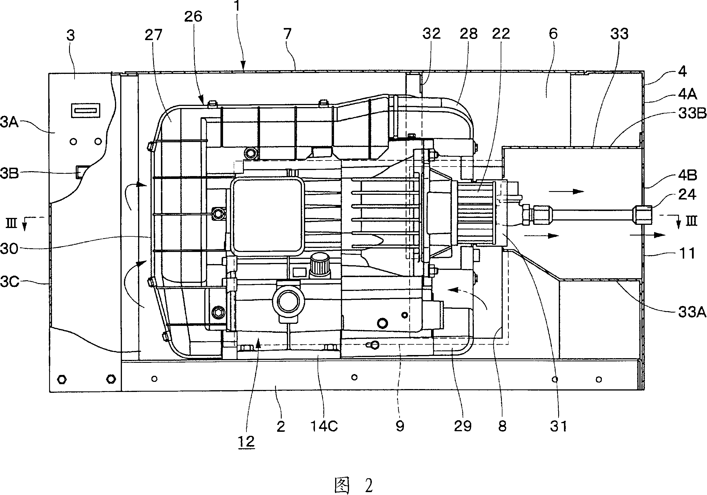
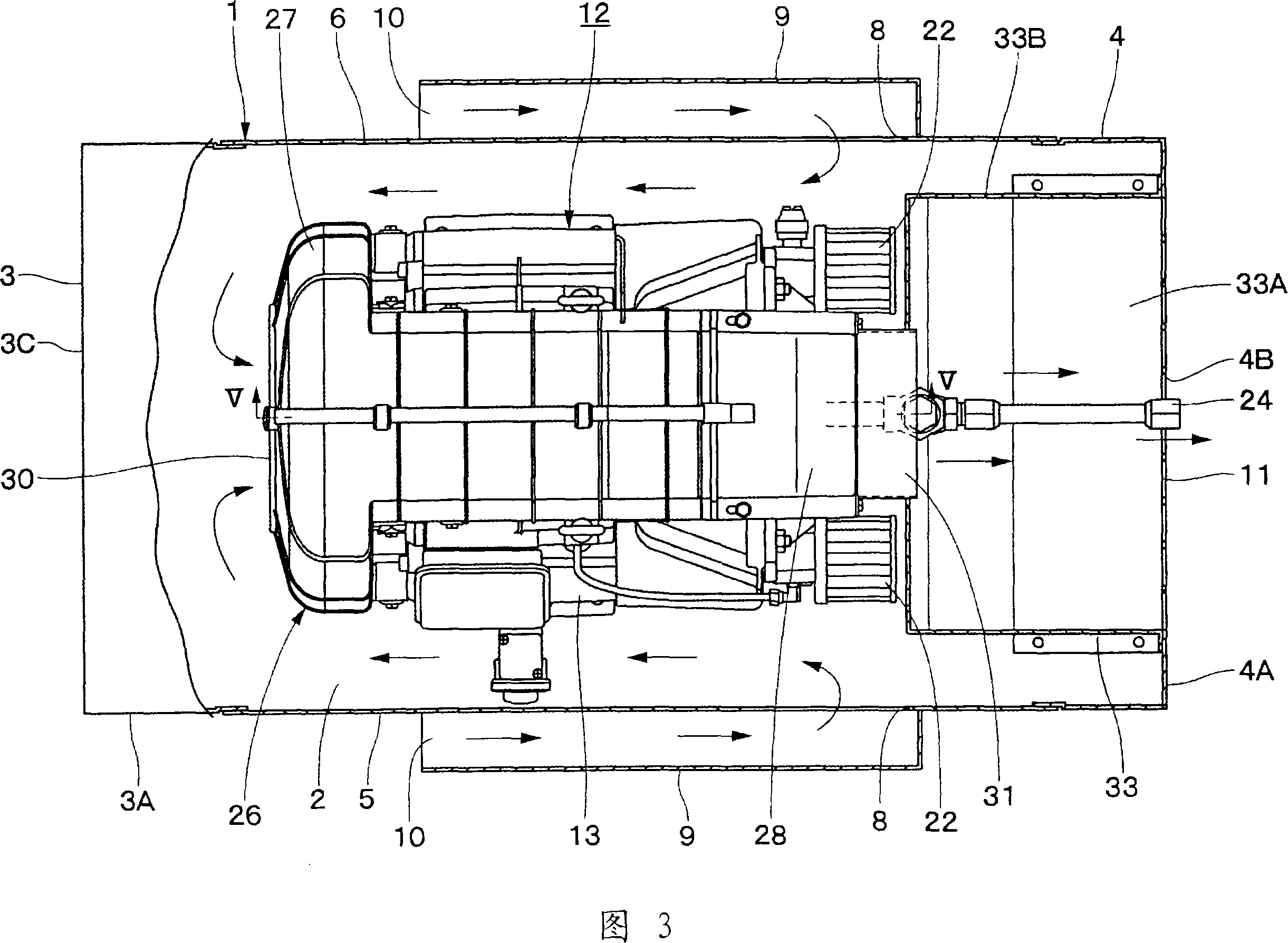
[0087] First, FIGS. 1 to 12 show a first embodiment of the present invention. In FIG. 1 , 1 denotes a package constituting the exterior of the packaged compressor. The package 1 is formed, for example, as a substantially cube-shaped box surrounded by a plurality of steel plates and the like, and has a soundproof structure. Moreover, as shown in FIGS. 1 to 4 , the package 1 is roughly composed of a base 2 on which a compressor main body 12 described later is mounted, a left panel 3 erected on the left side of the base 2 , and a right panel 3 erected on the right side of the base 2 . The panel 4, the front panel 5 arranged at the front between the left panel 3 and the right panel, the rear panel 6 and the top panel 7 integrally provided across the top surface from the back between the left panel 3 and the right panel 4 const...


PUM


Abstract

A sealing compressor improves the cooling efficiency of the main body of the compressor by circulating the cooling air in the seal. In the seal, an air intake for introducing the air from the outside to the inside of the seal is disposed at one terminal side opposite to the cooling air intake of a cooling air guide element in the axis direction. Therefore, the air introduced from the air intake is flowing in from the cooling air intake of the cooling air guide element via the circumference of the compressor main body. Moreover, the compressor main body can circulate the cooling air in the cooling air guide element from the inlet to the outlet. Therefore, the invention can efficiently cool the compressor main body by the cooling air flowing in the seal and in the cooling air guide element.

Description

technical field [0001] The present invention relates to, for example, a package-type compressor that includes a package that surrounds a compressor main body, a cooling air guide, and the like. Background technique [0002] In general, packaged compressors house a compressor body that compresses air, a cooling fan that circulates cooling air around the compressor body, and an air tank that stores compressed air discharged from the compressor body in a soundproof structure. composition in the package. Accordingly, during the compression operation, it is possible to reduce the noise caused by the compressor main body and the cooling fan, and to improve safety. [0003] In addition, as described above, it is the compressor main body including the motor, compression unit, cooling fan, etc. that generates noise, but the air tank itself does not generate noise. Furthermore, the air tank is larger than the compressor main body, and enclosing the air tank results in an increase in...

Claims


Application Information

Patent Timeline
IPC IPC(8): F04C18/02F04C29/04
CPCF04B35/04F04B39/066F05B2210/12F05B2220/20F05B2240/12F05B2260/962Y10S417/00
Inventor 井口治贞方康辅原岛寿和真土学三原宏之
Owner HITACHI LTD
Why Eureka
Try Eureka