Description point data acquiring method and device, description method and device

A technology for obtaining devices and drawing points, which is applied in image data processing, photolithography process exposure devices, instruments, etc., and can solve problems such as limited processing capacity, increased cost, and difficult substrate placement

Inactive Publication Date: 2008-04-02
FUJIFILM CORP
View PDF6 Cites 7 Cited by
  • Summary
  • Abstract
  • Description
  • Claims
  • Application Information

AI Technical Summary

Problems solved by technology

[0016] However, when the above-mentioned direct mapping method is performed, the above-mentioned inverse transformation is performed on all pixel position information of the transformed image data, and the calculation process of inverse transformation of the number of pixel data of the transformed image data must be performed, which sometimes requires a relatively long time. long time
In particular, in recent years, the resolution of image data to be processed tends to be higher and higher, and under this trend, image deformation processing as described above has a problem that the processing time becomes longer and longer.
[0017] In addition, in the existing image deformation processing method, since discontinuous addressing is necessary in the transmission of image data, if the rotation angle or deformation amount is large, the image rotation processing and scaling processing will be caused by discontinuous addressing. There are many places and time-consuming, and there is a problem that the time for image processing becomes longer in roughly proportion to the rotation angle or deformation amount
In particular, when the image data is compressed image data, as described above, the compressed image data needs to be decompressed every time the addressing is discontinuous, for example, the image data of different lines needs to be edited, and the edited image data is Compression, so image warping can be more time consuming if you add edit locations
[0018] Therefore, it is considered that as described in Patent Document 1, settings required for image rotation such as image size, rotation direction, and angle are performed in advance, and the settings are performed in advance before actual output processing, and in an exposure device utilizing a DMD, the DMD Although the inclination angle can be set in advance, in the exposure device, the substrate exposed by the DMD is placed on the stage that moves relatively to the DMD, and it is difficult to accurately align the substrate to the DMD and then place it. The variation of the moving stage, the substrate undergoing heat treatment and the deformation of the substrate itself, etc., so all these deformations cannot be considered in advance, so the method described in Patent Document 1 has the problem that it cannot be applied.
[0019] As described above, in the exposure apparatus using such a conventional DMD, since image deformation processing such as rotation processing and scaling processing takes time, in order to avoid this situation, it is necessary to increase the cost and improve the image processing capability.
[0020] For example, using a θ stage (rotary stage) as a stage on which a substrate is placed can allow accurate alignment at least for a tilt angle for a DMD, but the use of a θ stage has the problem of increasing the cost of the exposure device.
[0021] In addition, in order to perform image deformation processing such as time-consuming rotation processing or scaling processing in real time, it is also considered to use a dynamic support program (DSP), but when using DSP, the number of line buffers (line buffer) is limited. limited, so there is a problem of limited processing power
[0022] Furthermore, it is also considered to increase the processing capability (power) of computers such as personal computers (PCs) or the above-mentioned DSP, and there is a problem that the increase in power leads to an increase in cost.

Method used


Image

  • Description point data acquiring method and device, description method and device
  • Description point data acquiring method and device, description method and device
  • Description point data acquiring method and device, description method and device

Examples


Embodiment Construction

[0104] Hereinafter, the drawing point data acquisition method and device, and the drawing method and device according to the present invention will be described in detail with reference to preferred embodiments shown in the accompanying drawings.

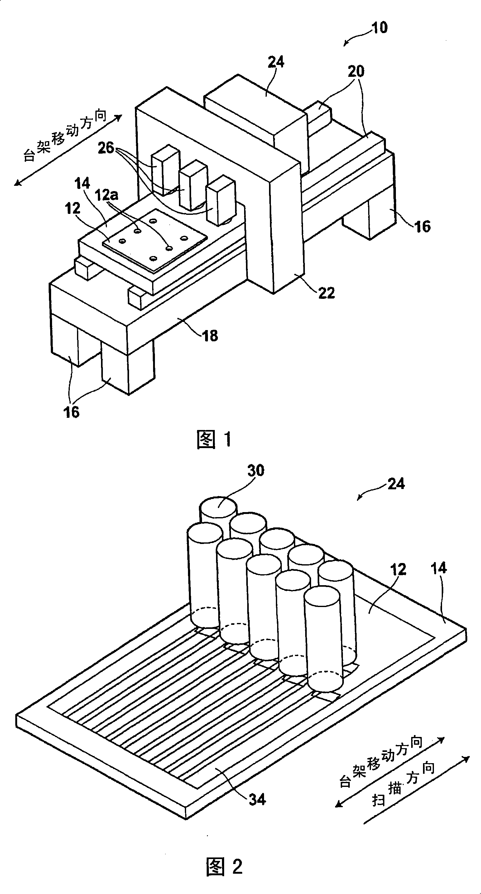
[0105] FIG. 1 is a perspective view showing a schematic configuration of an embodiment of an exposure apparatus to which a drawing apparatus of the present invention is applied for carrying out the drawing method of the present invention. The exposure device illustrated in the figure is a device for exposing various patterns such as wiring patterns of each layer of a multilayer printed wiring board, and is characterized in that the method of obtaining exposure point data used for exposing the pattern is first The schematic configuration of the exposure apparatus will be described.

[0106] As shown in FIG. 1 , the exposure device 10 includes: a rectangular plate-shaped moving stage 14, which is configured to absorb and hold the subs...


PUM


Abstract

The invention obtains the image data by processing deformation to the original image in multi-group in a different deforming processing condition beforehand. The invention selects a group of temporary deformation finished image data obtained in the deformation processing condition similar to the input deformation processing condition and processes the deformation to the selected temporary deformation finished image data based on the difference between the input deformation processing condition and the deformation processing condition of the selected temporary deformation finished image data, processes a deformation to the selected temporary deformation finished image data, takes the deformation finished image data as the tracing point data. Thereof, the invention provides a tracing point data obtaining method and the device thereof, a tracing method and the device thereof, which can inhibit the processing ability and obtain the exposure data for tracing the image with a low cost and a high smoothness even in the deformation processing with an increased deformation and a rotation or retraction of the image processing time.

Description

technical field [0001] The present invention relates to a method and device for obtaining image drawing point data. The original image data is deformed, and the deformed image data is obtained as drawing point data for drawing an image represented by the original image data on a drawing object. The invention relates to a rendering method and device for rendering an image represented by an original image on a rendering object based on acquired rendering point data. Background technique [0002] Conventionally, it is necessary to perform image deformation by rotating, enlarging, reducing, or freely deforming original image data, and obtaining image data after deformation. Various image deformation processing methods have been proposed for this purpose. [0003] As such an image deformation processing method, in Patent Document 1, in order to rotate a read image or an input image (original image data) in an image recording device such as a copier or a printer, for example, rota...

Claims


Application Information

Patent Timeline
Patent Type & Authority Applications(China)
IPC IPC(8): G03F7/20G06T3/40H04N1/387H01L21/30
CPCG06T3/608G06T3/20G06T3/00G06T3/60G06T11/00
Inventor 武者野满
Owner FUJIFILM CORP
Why Eureka
Try Eureka