Molding method and apparatus for making resin molded article

A technology of resin molding and molding method, which is applied in the fields of resin molding and foamed resin molding, and can solve problems such as no clear instructions on the beginning and end of foaming, decreased strength and rigidity of molded products, and enlarged foam area, etc., to achieve The product size and thickness are stabilized, the copying performance is excellent, and the effect of uniformity is realized

Inactive Publication Date: 2008-04-09
MAZDA MOTOR CORP
View PDF2 Cites 24 Cited by
  • Summary
  • Abstract
  • Description
  • Claims
  • Application Information

AI Technical Summary

Problems solved by technology

In addition, in the micro-foaming injection molding method using supercritical fluid, generally speaking, after the foamable molten resin is injected into the cavity, the supercritical fluid is released from the high-temperature and high-pressure state and foams instantaneously. In the case of compressing the mold before the end of fluid foaming so that the molten resin flows to the end of the cavity (full filling), it is necessary to control the compression of the mold in a very short time, for example, 1 second or less, so this operation is very difficult, and in fact also impossible
In addition, if the compression timing of the mold is wrong (later than the instantaneous foaming of the supercritical fluid), the area of ​​the foam tends to be enlarged, resulting in a decrease in the strength and rigidity of the molded product
In addition, in Patent Document 2, although there is a description that the compression of the mold starts about 0.02 seconds after the end of the injection, and the compression of the mold ends after about 0.08 seconds, how is this time control related to the start and end of the foaming of the foaming gas? This relationship is not clearly stated in Patent Document 2

Method used


Image

  • Molding method and apparatus for making resin molded article
  • Molding method and apparatus for making resin molded article
  • Molding method and apparatus for making resin molded article

Examples


Embodiment Construction

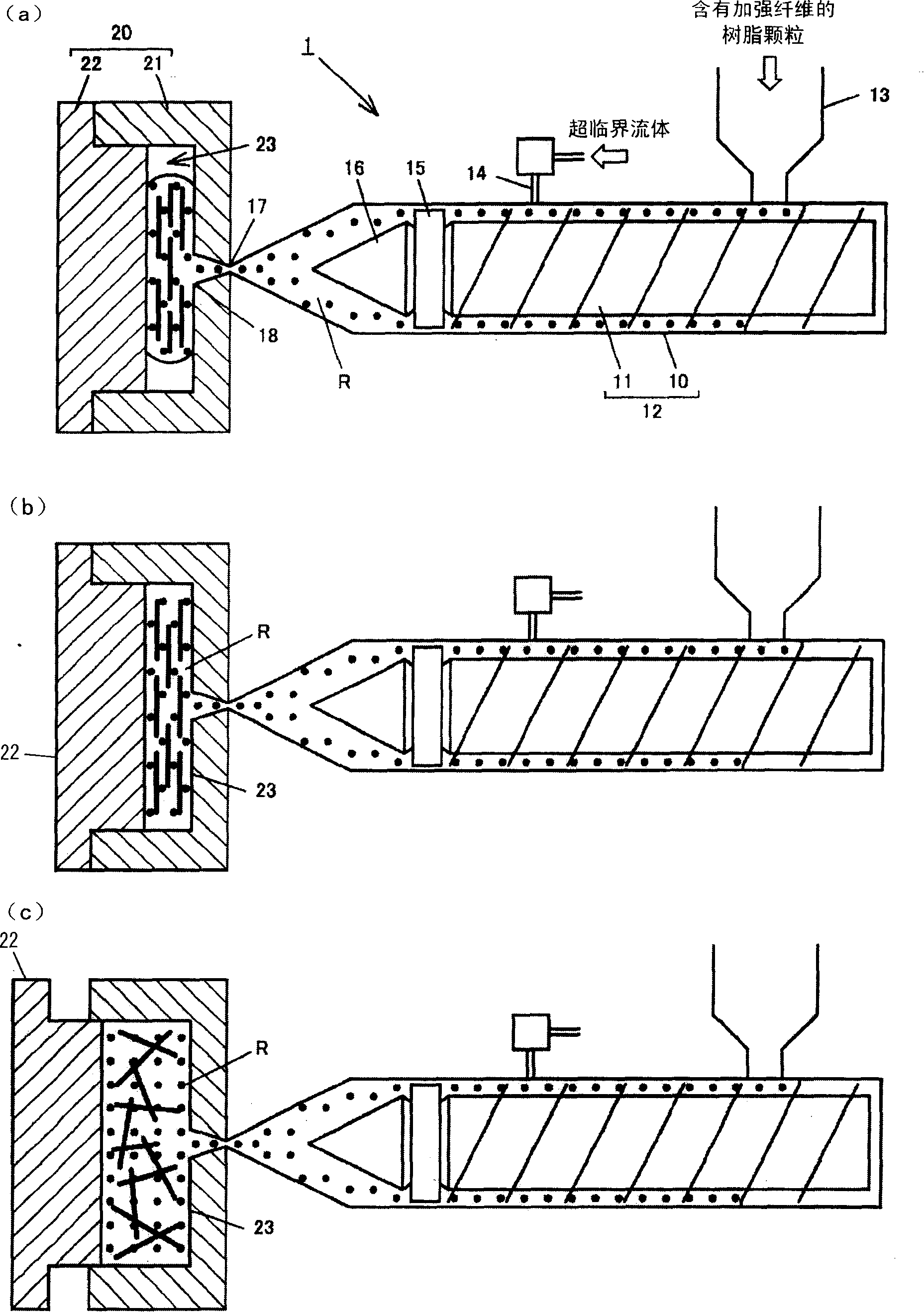
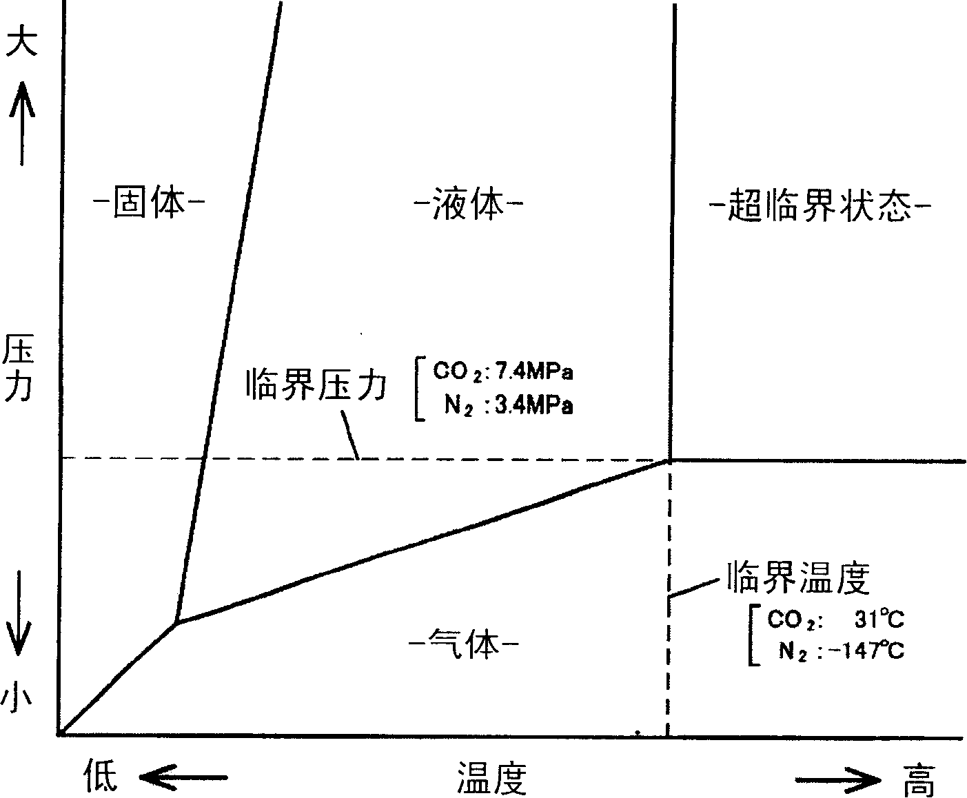
[0035] figure 1 It is an overall schematic diagram schematically showing the structure and operation of the molding apparatus 1 according to the present embodiment. The molding device 1 includes a screw feeder 12 (corresponding to the injection device of the present invention) including a laterally long outer cylinder (cylinder) 10 and a screw 11 and the like. In the vicinity of the start end of the screw feeder 12, a feed hopper 13 is provided through which resin pellets containing reinforcing fibers for reinforcing the resin molded product are fed, and near the terminal end of the screw feeder 12 is connected There is a supply pipe 14 for supplying supercritical fluid. The upstream side of the supply pipe 14 is connected to a gas cylinder of an inert gas such as nitrogen (N 2 ) and carbon dioxide (CO 2 ) through a supercritical fluid generation and supply device (not shown). The screw 11 includes a check ring 15 and a tapered head 16 provided at the front end thereof. On ...


PUM


Abstract

In the molding method of the resin molding product in the invention, the foamable molten resin (R) containing reinforcing fiber and supercritical fluid is injected into a cavity (23) with a short shot mode, the foamable molten resin (R) is made self-foam and flow in the cavity (23), the dimension of the cavity (23) is increased by expanding the molds (21 and 22) to the preset position thereby expanding the foamable molten resin (R) in the cavity (23). During the expansion working procedure the expanding of the foamable molten resin (R) is assisted by the gas vent, vacuum suction, and partial pressure adding to the foamable molten resin (R) with a gas or a resin, or beforehand packing the reinforcing fiber in the foamable molten resin (R). The foamable molten resin molding product which has no bulky space, can sufficiently expand to increase the volume and has an excellent duplicating capacity can be manufactured when the invention is used.

Description

technical field [0001] The present invention belongs to the technical field of resin molding, especially foamed resin molding. Background technique [0002] For components such as a door module carrier (a substrate when the door is modeled) constituting an automobile door, conventionally, in order to achieve weight reduction, high rigidity, cost reduction, and improvement of the door closing sound, etc. A foamed resin molded product is used. As for the technology of foaming resin molding, as shown in Japanese Patent Laid-Open Publication No. 7-9461 (hereinafter referred to as "Patent Document 1"), a heat-expandable thermoplastic resin (heat-expandable resin) in a molten state is ), completely fill the cavity formed by the mold set on the vacuum suction channel in the closed state, and immediately after the surface layer of the molded body is formed, vacuum suction is performed to increase the volume of the cavity, thereby making the above The heat-expandable resin is foame...

Claims


Application Information

Patent Timeline
Patent Type & Authority Applications(China)
IPC IPC(8): B29C45/56B29C45/17B29C45/76B29C45/63B29C45/57B29C45/04
CPCB29C45/1705B29C45/1706
Inventor 金子满晴枥冈孝宏小川淳一
Owner MAZDA MOTOR CORP
Why Eureka
Try Eureka