End-yarn insertion device

A technology of inserting device and end yarn, which is applied in the direction of clothing, apparel, textiles and papermaking, etc., which can solve problems such as insufficient yarn tension, excess yarn tension, loose knitting yarn, etc., to prevent grip damage and prevent the number of parts from increasing , The effect of preventing the deviation of clamping timing

Inactive Publication Date: 2008-04-09
SHIMA SEIKI MFG LTD
View PDF1 Cites 4 Cited by
  • Summary
  • Abstract
  • Description
  • Claims
  • Application Information

AI Technical Summary

Problems solved by technology

[0004] In the prior art end yarn inserting device, since the end yarn hook is lifted from the catch position to clamp the end yarn, when clamping before the end yarn is released by the cutting and holding device, excess yarn tension acts on the knitting yarn. This may cause disconnection
And when the clamping device releases the end yarn while cutting and clamping, the yarn tension applied to the end yarn becomes insufficient, and the knitting yarn becomes loose
In addition, there is a case where the end yarn protrudes from the end yarn hook, and thus the insertion of the end yarn into the finger pocket is unstable.

Method used


Image

  • End-yarn insertion device
  • End-yarn insertion device
  • End-yarn insertion device

Examples


Embodiment Construction

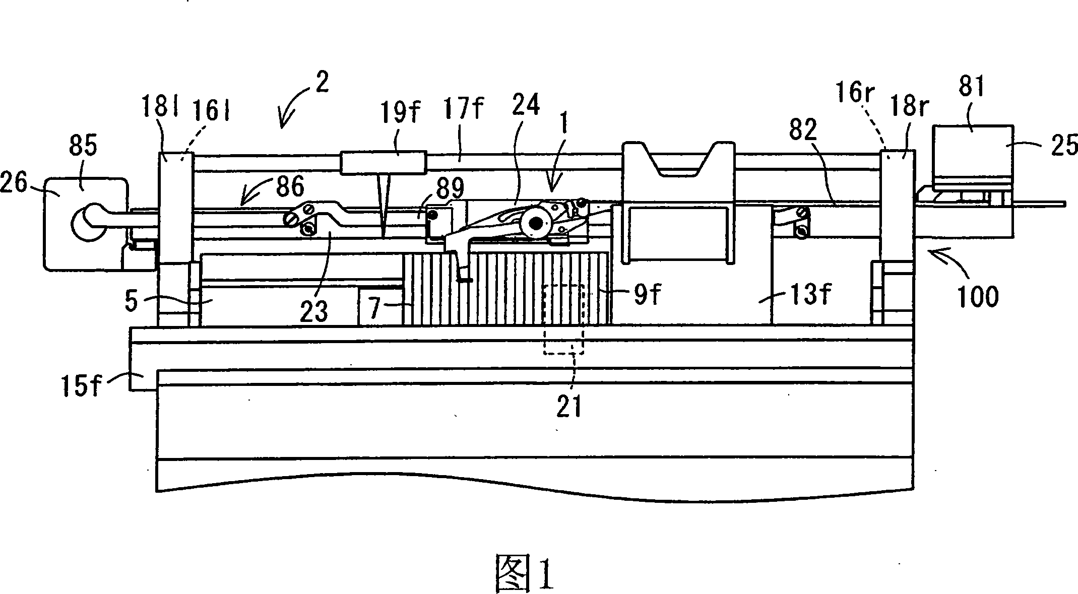
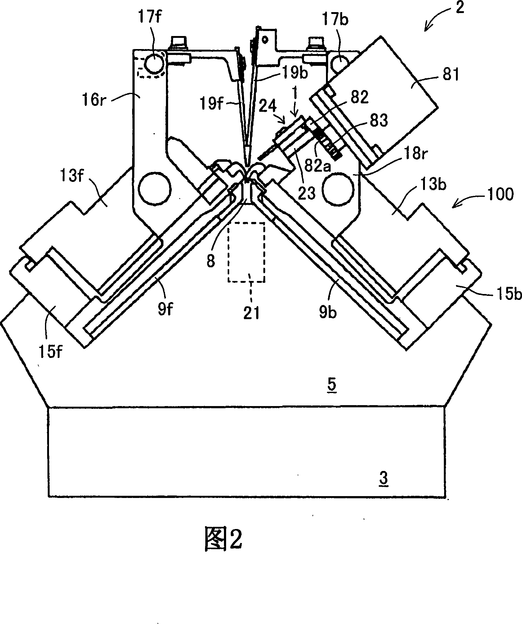
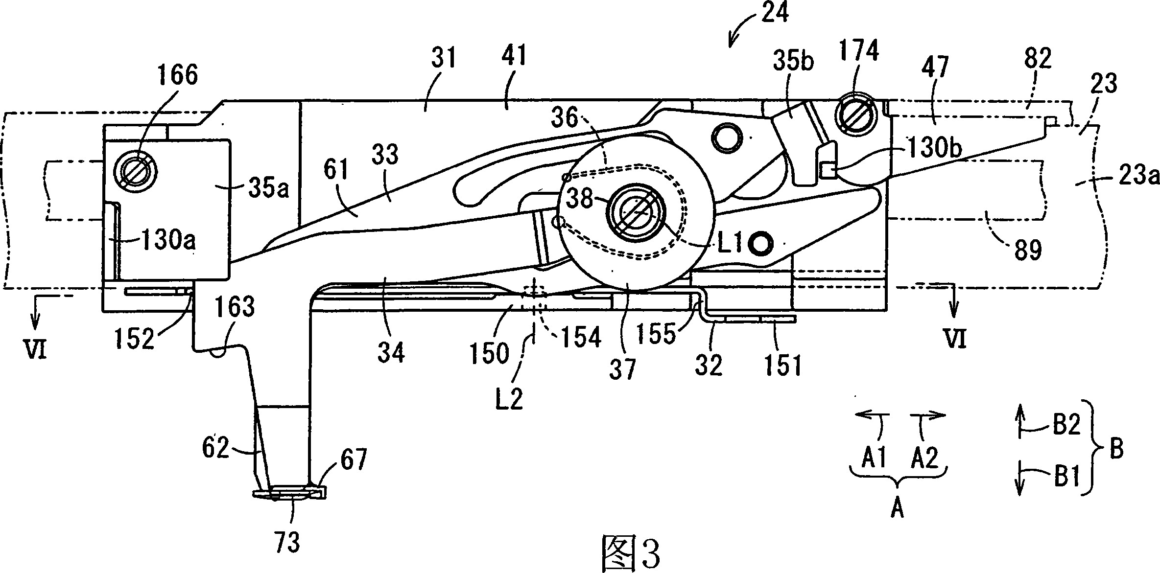
[0022] Hereinafter, embodiments for carrying out the present invention will be described with reference to the drawings. Fig. 1 is a front view showing a glove knitting machine 2 having an end yarn insertion device 1 as one embodiment of the present invention. FIG. 2 is a side view showing the glove knitting machine 2 . The glove knitting machine 2, which is a type of flat knitting machine, includes a knitting machine main body 100 for knitting knitted fabrics, a cutting holding device 21, and an end yarn inserting device 1 .

[0023] The knitting machine main body 100 has a pair of chassis 3 provided facing each other, and a mountain-shaped support stand 5 extending along both ends of the pair of chassis 3 in the left-right direction and protruding upward is provided. On the support table 5, a pair of front and rear needle beds 9f, 9b extending in the left-right direction are provided so as to accommodate the plurality of knitting needles 7 freely. A pair of front and rear ...


PUM


Abstract

The invention provides an end yarn insertion device which clamps the end yarn to insert into the internal of knitted fabrics. End yarn insertion device (1) is set on a flat knitting machine for glove (2), with a guide track (23) and a base (31) sliding transitionally along the guide track (23). The base (31) is equipped with a movable object (32) shifting relatively relative to the base (31). Themovable object (32) is equipped with an end yarn hook (33) and an end yarn pressing foot (34). The end yarn hook (33) shifts between the capture position of capture yarn and the hook backoff positionof knitting needle backoff. The end yarn pressing foot (34) acts continuously with the end yarn hook (33), shifting on the clip position where it coordinates with the end yarn hook on the capture position to span support position supporting yarn captured by the end yarn hook and on the pressing foot backoff position where it yields with the knitting needle and the end yarn hook (33). A second driving mechanism (26) drives the end yarn hook (33) to shift between the capture position and the hook backoff position. The base (31) is equipped with a stopper (48). The stopper (48) jams and fixes the end yarn pressing foot(34) shifting from the pressing foot backoff position to the support position to prevent shifting, ensure that the end yarn pressing foot stands by on the stand-by position where the yarn of yarn feeding yields. And the end yarn pressing foot (34) is detached from the stopper (48) by shifting the movable object (32) relatively relative to the base(31).

Description

technical field [0001] The present invention relates to an end yarn inserting device provided on a flat knitting machine for inserting an end yarn into the inner side of a bag-shaped knitted fabric. Background technique [0002] The end yarn inserting device in the prior art moves the end yarn hook and the end yarn presser near the transition yarn when the end yarn is clamped. Next, the end yarn hook and the end yarn presser are swung. At this time, the end yarn hook descends to the catching position for catching the transitional yarn, and the end yarn presser separates upward relative to the end yarn hook. In this state, the end yarn of the transition yarn is caught on the end yarn hook. Then, the gripping of the end yarn by the cutting and gripping device is released, and the end yarn hook is raised, and the end yarn of the intermediate yarn is clamped by the end yarn hook and the end yarn presser foot (for example, refer to Patent Document 1). [0003] Patent Document ...

Claims


Application Information

Patent Timeline
Patent Type & Authority Applications(China)
IPC IPC(8): D04B15/00
CPCA41D19/04D04B1/28D04B7/34D04B15/44D04B15/48D04B15/56D04B35/14D10B2501/041
Inventor 宫井卓哉
Owner SHIMA SEIKI MFG LTD
Why Eureka
Try Eureka