

Guiders, method for regulating throat flow area and turbine engine thereof
A flow area and guide technology, applied in the direction of machines/engines, engine components, mechanical equipment, etc., can solve the problems of low efficiency, weight increase, leakage loss, etc., and achieve the effect of high efficiency and simple structure
Inactive Publication Date: 2008-04-09
BEIHANG UNIV
View PDF0 Cites 9 Cited by
- Summary
- Abstract
- Description
- Claims
- Application Information
AI Technical Summary
Problems solved by technology
[0006] The above-mentioned prior art has at least the following disadvantages: due to the existence of circumferential transmission parts, the weight is increased and the structure is complicated, and because the guide vane 1 is installed dynamically, there is a gap leakage loss and the efficiency is low
Method used
View moreImage
Smart ImageViewing Examples

Examples
specific Embodiment
[0025] Concrete embodiment, as shown in table 1:
[0026] Table 1 Flow change at the throat obtained by air injection
[0027] Flow(kg / m.s)
[0028] During the implementation of the present invention, the flow control mechanism and controllable range can be analyzed by means of numerical simulation and according to the simulation results. The control form is determined according to the internal flow conditions of the guider and the flight requirements, and the variation range of the jet total pressure is obtained. It can also be verified by the cascade experiment, and the required structure of the jet is given.
Login to View More PUM
 Abstract
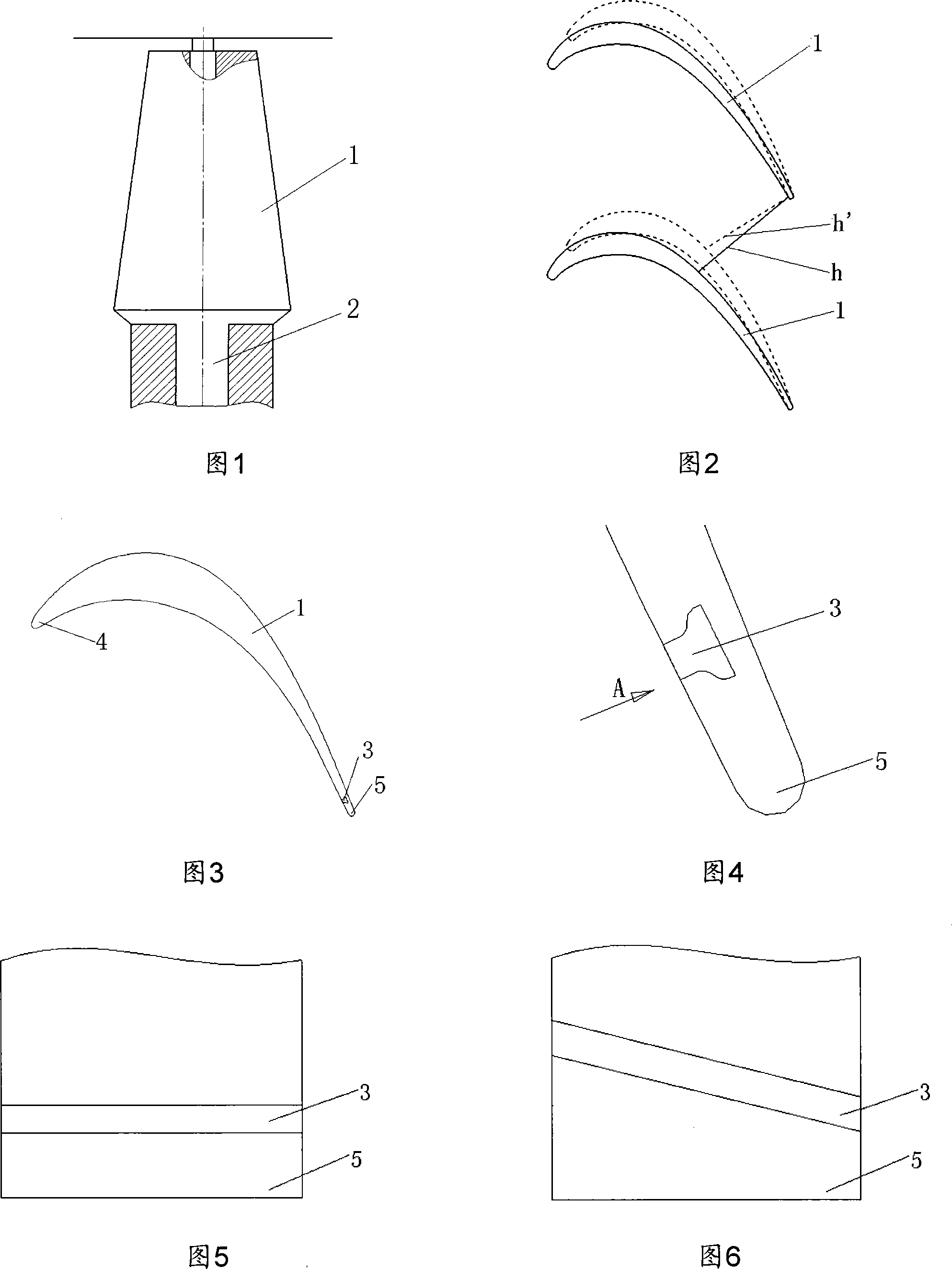
The invention discloses a guide, a method used for adjusting the circulation area of the throat and a turbine engine. The tail on the pressure surface of a guide vane of the guide is provided with a pore; the distance from the pore to the tail of the guide vane is equal to 4% to12% of the linear distance between the tail of the guide vane and the head of the guide vane. The circulation area of the throat is changed by spraying the air into the rear of the throat of the guide through the pore. The total pressure of the jet can be continuously changed in order to implement continuous adjustment of the throat area of the guide, avoid the loss of the leakage flow of a vane tip and reduce the separation of a suction surface. The invention has the advantages of simple structure and high efficiency, and is especially suitable for a variable cycle turbine engine, etc.
Description
technical field [0001] The invention relates to a turbine engine, in particular to a guider of the turbine engine, a method for adjusting throat flow area and the turbine engine. Background technique [0002] When the flight mission includes a wide range of Mach numbers, or requires better performance at multiple operating points in the flight envelope, it is necessary to design a variable cycle engine that maintains good performance under different operating conditions and thermal cycles. [0003] Variable cycle engines are generally realized by changing the geometric characteristics of components. The throat area of the guide of the turbine engine directly affects the air flow through the engine, which makes the throat area of the guide one of the main adjustment parameters. [0004] As shown in FIG. 1 , the way to adjust the throat area of the guide in the prior art is to adjust the installation angle of the guide vane 1 . Specifically, the rotating shaft 2 is rad...
Claims
Login to View More Application Information
Patent Timeline
 IPC IPC(8): F01D9/02F01D17/16
Inventor 刘火星邹正平杨旸
Owner BEIHANG UNIV