
Soil body image real time capturing method and system used for centrifugal machine model trial

A centrifuge model and real-time acquisition technology, applied in the direction of optical devices, measuring devices, instruments, etc., can solve the problems of inability to capture the destruction process continuously, difficult to analyze and process, and image quality interference, so as to avoid the interference of strong electromagnetic fields, Realize remote control and improve the effect of gray scale difference

Active Publication Date: 2008-04-09
TSINGHUA UNIV
View PDF0 Cites 22 Cited by
  • Summary
  • Abstract
  • Description
  • Claims
  • Application Information

AI Technical Summary

Problems solved by technology

However, the current measurement equipment, or the use of photographic technology and a digital camera placed in the centrifuge, can only collect intermittent pictures and cannot continuously capture the destruction process (White D J, Take W A, Bolton M D. Soil deformation measurement using particle image ve] ocimetry (PIV) and photogrammetry.Geotechnique, 2003, 53 (7): 619-631.); or through the slip ring, the image collected by the low-speed camera is transmitted to the control room outside the centrifuge for storage, which is limited by the slip ring to the transmission rate. The resolution of the image is often small, and the image is affected by the strong electromagnetic field when it passes through the high-speed rotating slip ring, the image quality is seriously disturbed, and it is difficult to be used for analysis and processing (Zhang Ga, Mou Taiping, Zhang Jianmin. Based on image analysis Measurement of deformation field of soil slope centrifugal model test. Chinese Journal of Geotechnical Engineering, 2007, 29(1): 94-97.)

Method used


Image

  • Soil body image real time capturing method and system used for centrifugal machine model trial
  • Soil body image real time capturing method and system used for centrifugal machine model trial

Examples


Embodiment Construction

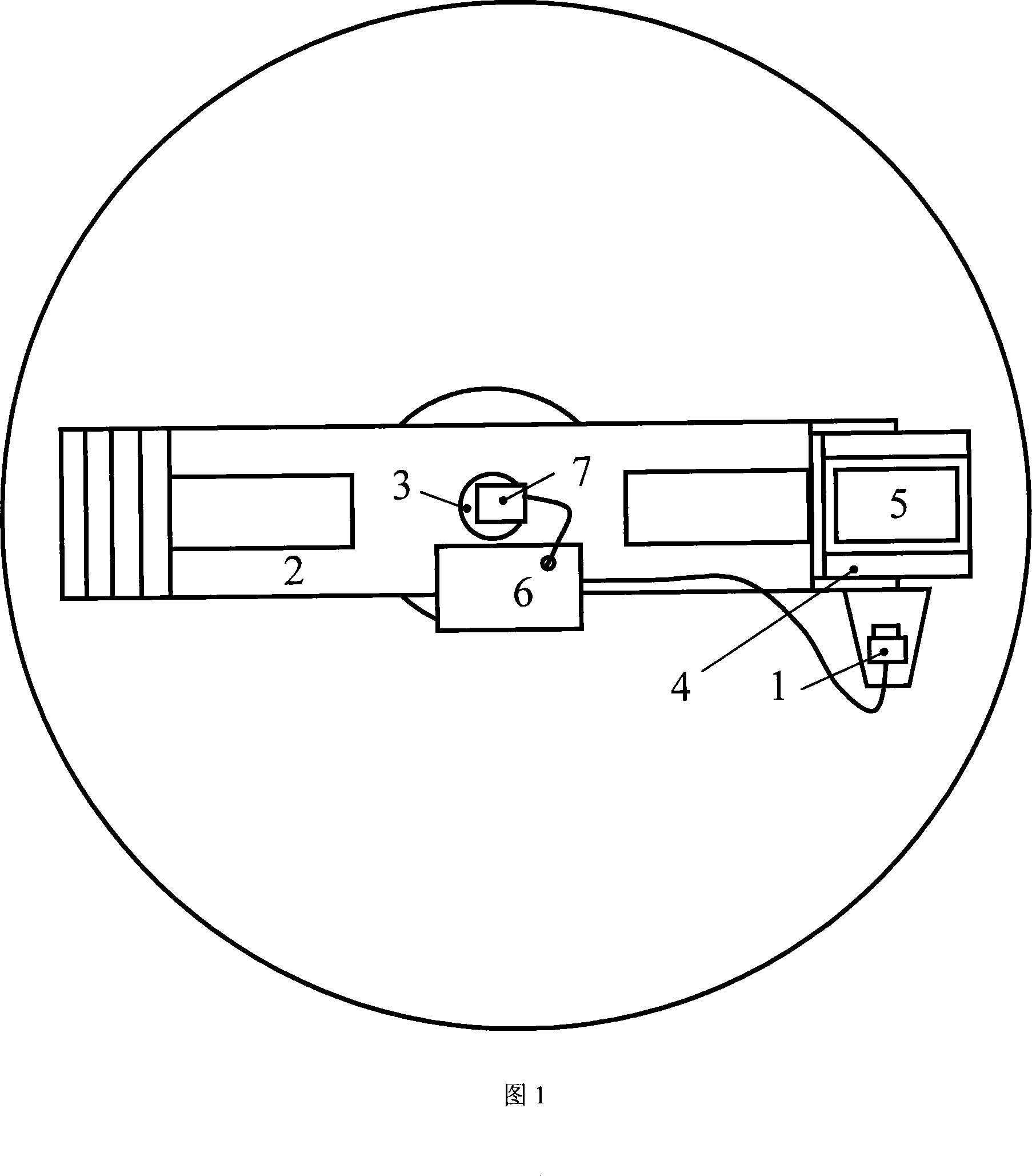
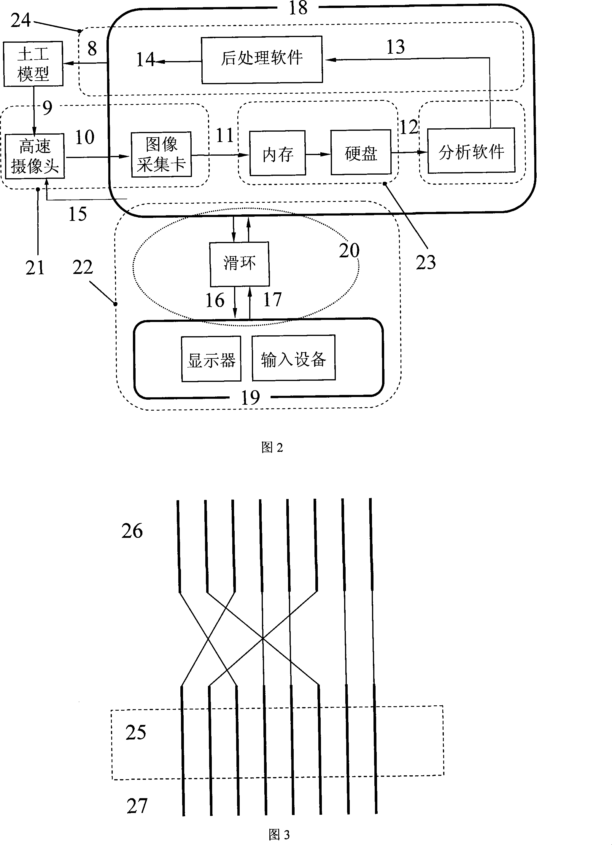
[0021] The principle, structure and working process of the present invention will be further described below in conjunction with the accompanying drawings.

[0022] Fig. 1 is a schematic layout diagram of a real-time soil image acquisition system for a centrifuge model test provided by the present invention. To solve the problem of real-time high-quality storage of large-flow data collected during the centrifuge model test, the interference of the centrifuge slip ring must first be overcome. The centrifuge slip ring is also called a collector ring, which is a device similar to a brush. As a channel for internal and external data, current, etc. during the rotation of the centrifuge. When the slip ring rotates at high speed, a strong electromagnetic field will be generated inside it, and its own structural characteristics determine that the signal transmitted through it will inevitably be seriously affected in terms of transmission speed and quality, so the only way to avoid sl...


PUM


Abstract

The invention provides a soil body image real-time acquisition method and system used for a centrifuge model test and belongs to geotechnical engineering test and measuring technology field. By installing computers on a swiveling jib of the centrifuge, the invention finishes the acquisition and storage of the image in the centrifuge, avoids the interference of a strong electromagnetic field in a slip ring and ensures the quality of the collected image, thus the precision of the analysis is improved effectively; the combining use of a high-speed camera and a way of step storing that the image is first stored in real time into an internal memory and then restored into a hard disc realizes the acquisition and real-time storage of image series with high-speed and strong resolution when the centrifuge is running; by using a LAN built by a cross network cable passing through the slip ring of the centrifuge, the interference of the strong electromagnetic field in the slip ring caused by high-speed rotation of the centrifuge can be overcome, thus realizing real-time control of the computers by a control room, and meanwhile pictures shot by the high-speed camera are mapped onto a monitor of a control machine.

Description

technical field [0001] The invention relates to a real-time soil image acquisition method and system for a centrifuge model test, belonging to the technical field of geotechnical engineering test and measurement. Background technique [0002] Geotechnical centrifuge model test is one of the widely used research methods in geotechnical engineering, and its test and measurement technology has been widely valued in recent years. However, the displacement measurement in the traditional centrifugal model test has defects such as heavy workload, low measurement accuracy, limited measurement points, and large disturbance to the model. [0003] The non-contact displacement measurement technology obtains the displacement image of the model during the loading process through electronic camera equipment, and through the principle of correlation analysis, the displacement field of the slope surface at any time can be obtained. To a large extent, it has overcome the above-mentioned prob...

Claims


Application Information

Patent Timeline
IPC IPC(8): G01B11/00G01C11/00
Inventor 张嘎胡耘张建民
Owner TSINGHUA UNIV
Learn More