Portable power supply adapters

A portable power supply and adapter technology, applied in the direction of rotating collectors, collectors, circuits, etc., can solve the problems of disorganized storage and carrying, inconvenient use, uncoordinated appearance of power adapters and computers, etc.

Inactive Publication Date: 2008-04-09
吕王华
View PDF0 Cites 7 Cited by
  • Summary
  • Abstract
  • Description
  • Claims
  • Application Information

AI Technical Summary

Problems solved by technology

The power cords of the existing power adapters are all connected outside the main part of the adapter. Because the power cords are long, they tend to become messy and inconvenient when storing and carrying them. Especially in some miniaturized products, the adapter part The space occupied is often close to or even exceeds the space occupied by these products. For example, the notebook computer is now smaller and smaller, and it is very convenient to carry, but its corresponding power adapter is still the same as before, or just put the main body of the adapter The size is reduced, but the power cord and its connection method have not changed. When storing and carrying, the power adapter takes up a lot of space, which makes it inconvenient to use. In addition, the appearance of the power adapter and the computer itself is also uncoordinated.

Method used


Image

  • Portable power supply adapters
  • Portable power supply adapters
  • Portable power supply adapters

Examples


Embodiment 1

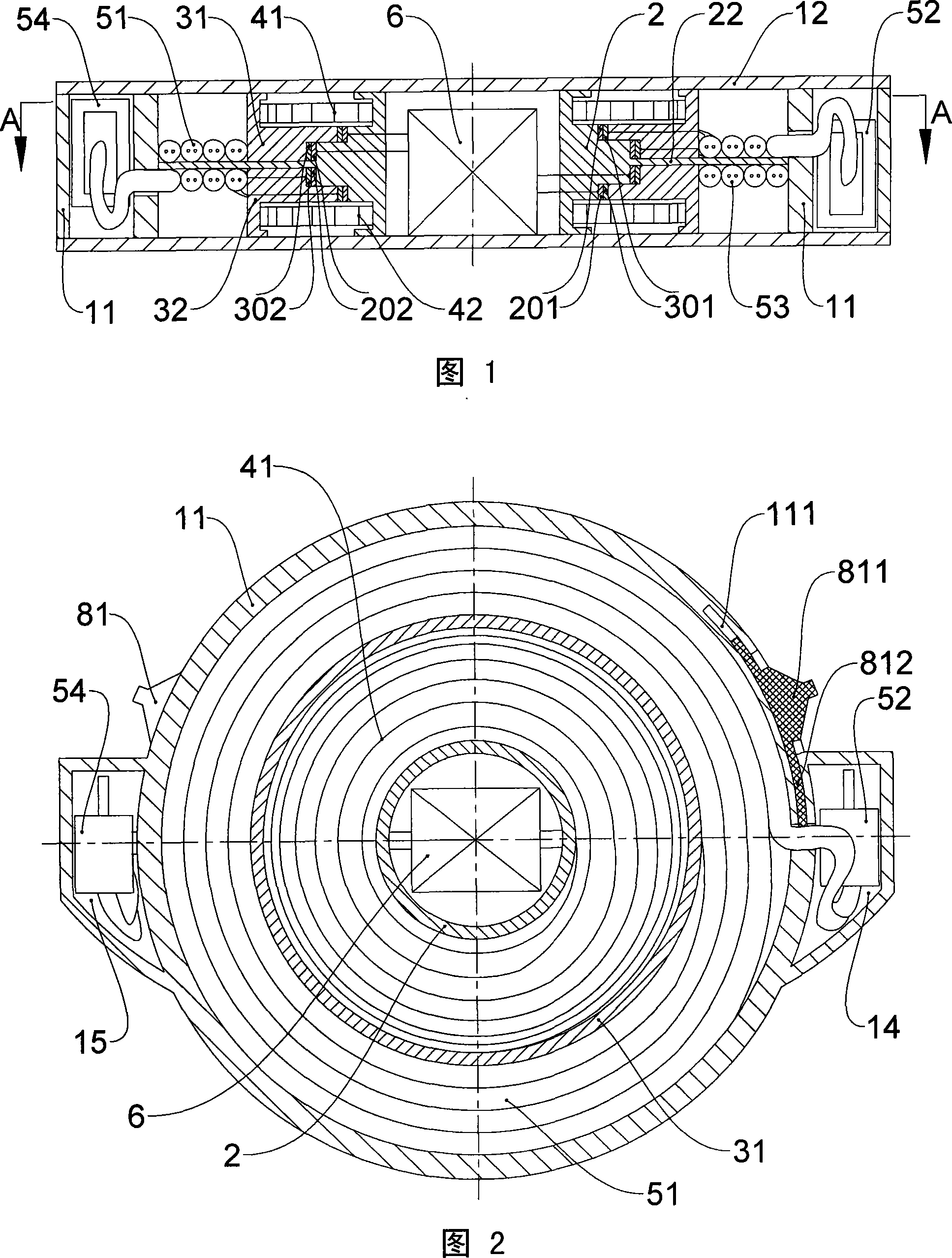
[0023]As shown in Figures 1 and 2, the present invention includes a housing, a power input line 51, a power input plug 52, a power output line 53, a power output plug 54, a power conversion circuit 6, and a wire locking mechanism. The housing includes Side walls 11, upper and lower end covers 12, two plug compartments 14, 15 are arranged on the housing, and the power input plug 52 and the power output plug 54 are respectively placed in the plug compartments 14, 15. The center of the housing is provided with a fixed hollow shaft 2, the power conversion circuit 6 is located in the hollow of the shaft 2, the shaft 2 is a stepped shaft symmetrical in the axial direction, and the shaft 2 The outside of the side wall of the side wall is provided with an annular partition 22 at the axial center, the top of the annular partition 22 is provided with an upper turntable 31, and the bottom is provided with a lower turntable 32. The outer circumference of the upper turntable 31 and the lowe...

Embodiment 2

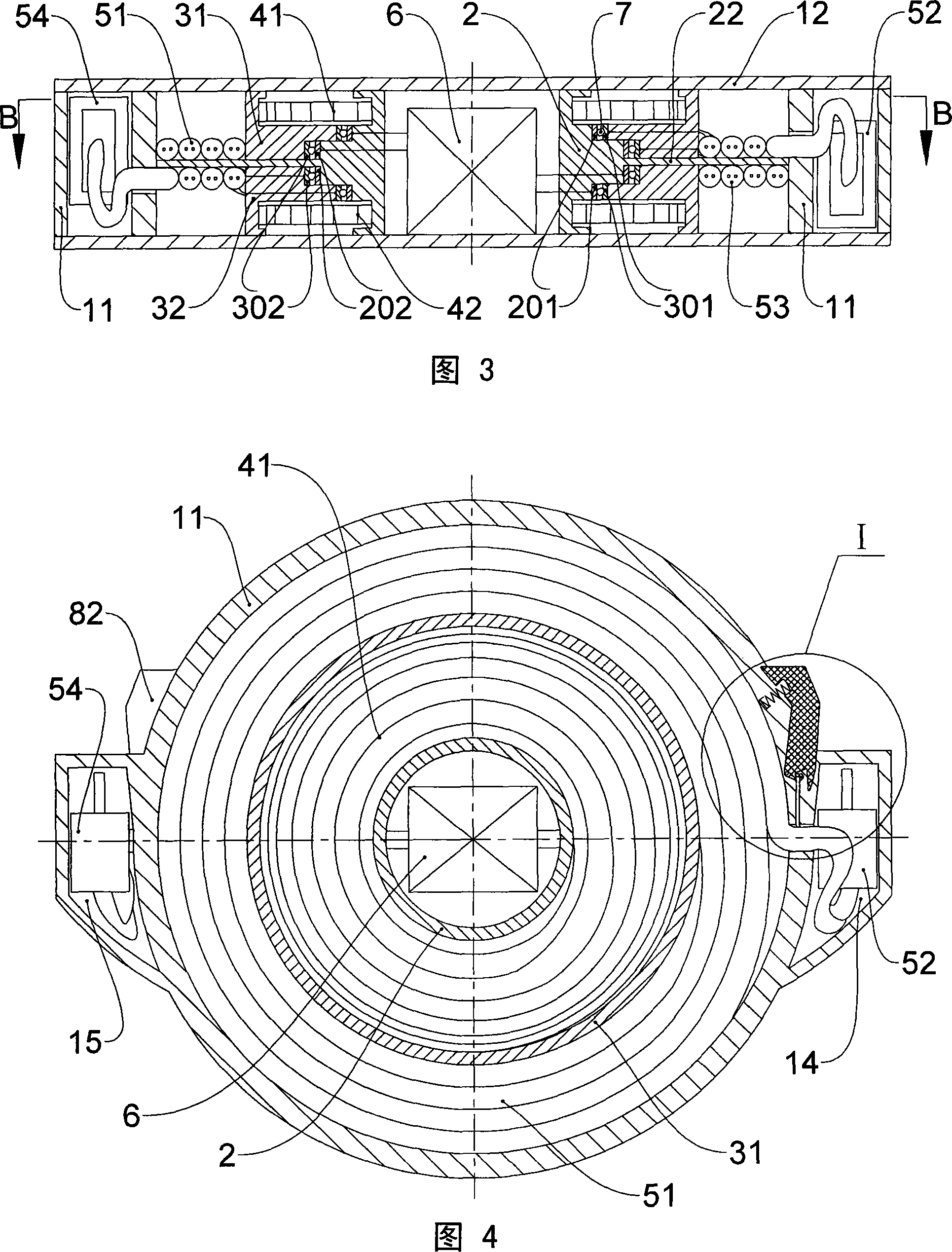
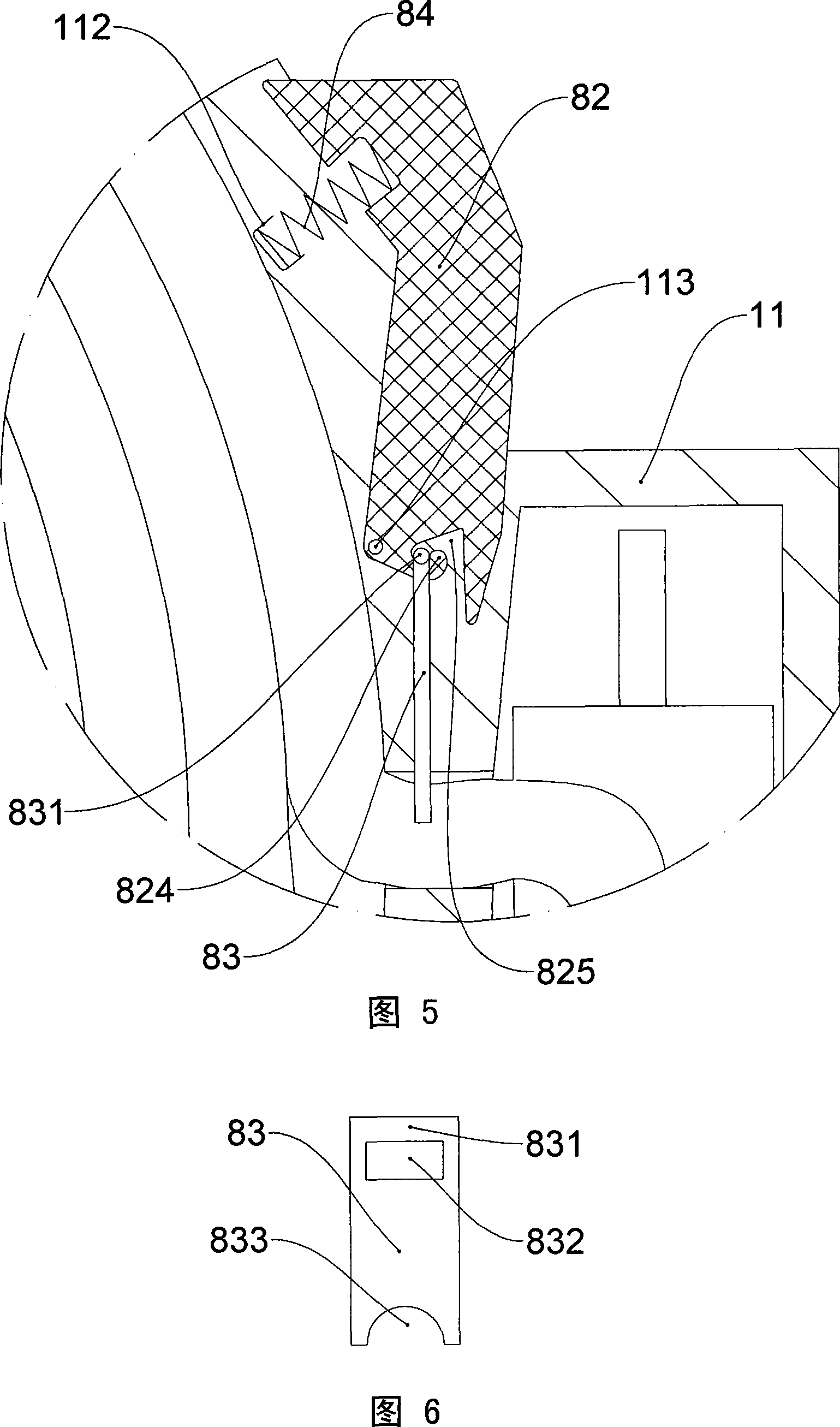
[0025] As shown in Fig. 3, Fig. 4, Fig. 5 and Fig. 6, the difference between this embodiment and Embodiment 1 lies in: the wire locking mechanism and the outer conductive layers 301, 302 and the inner conductive layers 201, 202 The connections between them are different. The wire locking mechanism in this embodiment includes a pressing piece 82, a pressing piece 83, and a compression spring 84. One end of the compression spring 84 is connected to the positioning part 112 on the housing, and the other end is connected to the pressing piece. 82 is connected to the upper part, and the lower part of the pressing part 82 is rotatably connected to the fixed shaft 113 located on the housing. The bottom of the pressing part 82 is provided with a hook 824 and a guide groove 825. The pressing part 83 is provided with a shaft portion 831, a perforation portion 832, and a crimping portion 833, the hook 824 passes through the perforation portion 832 and clamps the shaft portion 831, and th...


PUM


Abstract

The invention discloses a portable power adapter which has small occupied space, aesthetic and harmonic appearance, and convenient deploying and collecting and carrying. The invention comprises a housing, a power input and an output line (51, 53), a power convention circuit (6), and a wire lock-up mechanism; the center of the housing is provided with a hollow stepped shaft column (2), the external sidewall of the shaft column (2) is provided with a ring diaphragm (22), an upper and a lower rotating disc (31, 32) is provided above and below the ring diaphragm (22), the stepped column surface of the upper and the lower rotating discs are respectively provided with external conducting layers (301, 302), the shaft column (2) is provided with an inner conducing layers (201, 202), the power input and the output lines (51, 53) are connected with the external conducting layers (301, 302) respectively, the input and the output ends of the power convention circuit (6) are connected with the inner conducting layers (201, 202), an upper and a lower twisting spring (41, 42) are connected between the upper and the lower rotating discs (31, 32) and the shaft column (2), and the power input and the output lines (51, 53) are wound the periphery of the upper and the lower rotating discs (31, 32).

Description

technical field [0001] The invention relates to a portable power adapter. Background technique [0002] At present, power adapters are widely used in electronic products, household appliances, notebook computers and other products to obtain the rated voltage and current required for the product to work. The power cords of the existing power adapters are all connected outside the main part of the adapter. Because the power cords are long, they tend to become messy and inconvenient when storing and carrying them. Especially in some miniaturized products, the adapter part The space occupied is often close to or even exceeds the space occupied by these products. For example, the notebook computer is now smaller and smaller, and it is very convenient to carry, but its corresponding power adapter is still the same as before, or just put the main body of the adapter The volume is reduced, but the power cord and its connection method are not changed. When retracting and carrying, t...

Claims


Application Information

Patent Timeline
Patent Type & Authority Applications(China)
IPC IPC(8): H01R13/72H01R13/60H01R39/64B65H75/34
Inventor 吕王华
Owner 吕王华
Why Eureka
Try Eureka