Heat radiator for liquid cooling type heat radiating device

A technology of heat dissipation device and liquid cooling, applied in cooling/ventilation/heating transformation, instrument cooling, instrument and other directions, it can solve the problems of uneven flow velocity distribution, fluid stagnation, affecting the heat soaking effect, etc.

Active Publication Date: 2008-04-09
NAT CENT UNIV
View PDF0 Cites 16 Cited by
  • Summary
  • Abstract
  • Description
  • Claims
  • Application Information

AI Technical Summary

Problems solved by technology

[0005] Looking at the above two structures, it is intended to use most of the ribs 14, 26 to increase the contact area between the working fluid and the radiator to achieve sufficient heat transfer effect, but the fluid flows independently between the channels 15, 27, and the working fluid between the channels 15, 27 are not connected to each other, so the temperature of the working fluid in each channel 15 and 27 cannot be evenly distributed
[0006] In addition, because each channel 15, 27 flows in a single flow direction, and is affected by th...

Method used


Image

  • Heat radiator for liquid cooling type heat radiating device
  • Heat radiator for liquid cooling type heat radiating device
  • Heat radiator for liquid cooling type heat radiating device

Examples


Embodiment Construction

[0025] The foregoing and other technical contents, features and effects of the present invention will be clearly presented in the following detailed description of four preferred embodiments with reference to the drawings.

[0026] For convenience of description, in the following embodiments, the same or similar elements are denoted by the same reference numerals.

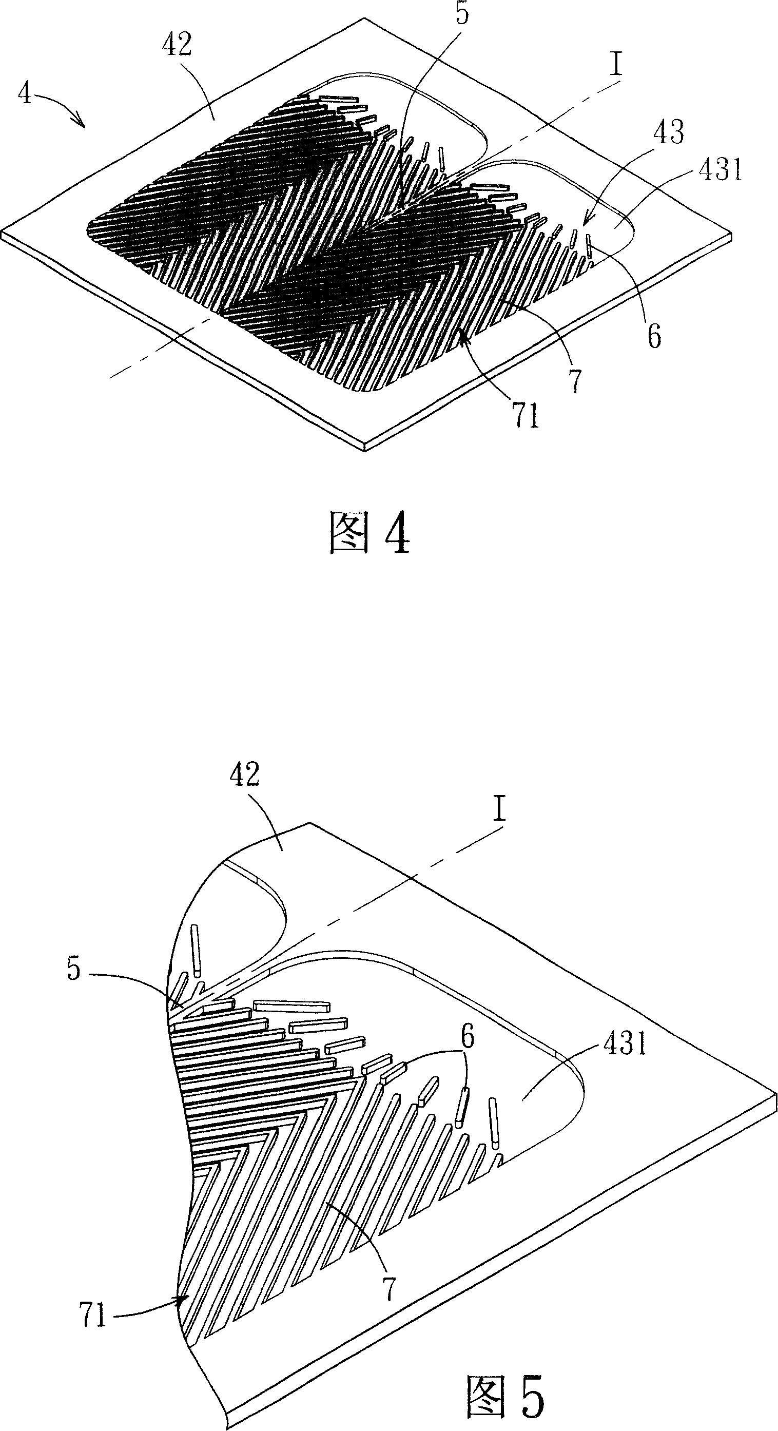
[0027] See Figure 4 to Figure 7 , The first preferred embodiment of the heat sink of the liquid-cooled heat sink of the present invention includes a housing unit 4, a partition plate 5, and a plurality of interfering elements. The housing unit 4 is made of heat-conducting material and forms an accommodating space 43. The housing unit 4 has an upper plate 41 and a lower plate 42 matched with the upper plate 41. The upper plate 41 Two water outlets 411 that communicate with the accommodating space 43 are formed on the top; the partition plate 5 is located on the center line L1 of the accommodating space 43, and the...


PUM


Abstract

The invention discloses a radiator of a liquid cooling heat radiation device, which is hot connection with a heat source of electronic equipment and is used by working fluid. The invention includes a shell unit and a plurality of interference elements. The shell unit is made of heat conducting material and forms a containing space. The shell unit has two water openings communicated with the containing space for working fluid in and out. The interference elements is equipped in a flow passage and the working fluid in flowing with the mode of full blending, constant flowing direction change, continuous boundary layer development and damage can improve heat transfer effect and heat radiation performance of the radiator.

Description

technical field [0001] The invention relates to a radiator, in particular to a radiator of a liquid-cooled radiator. Background technique [0002] Referring to Fig. 1, the working mode of the liquid-cooled radiator is mainly to use a radiator 1 to be arranged on a heat source 17 (Heat Source) such as an electronic device, and to use a pump 18 (Pump) as a power source to make the working fluid dissipate heat The device 1 flows and circulates to a heat sink 19 (Heat Sink), so as to bring the heat energy of the heat source 17 to a heat sink 19, and a fan 191 (Fan) is used to accelerate the heat dissipation of the heat sink 19 to the outside, and the liquid is cooled The advantage of the heat dissipation device is that the high-flux heat can be quickly transferred to the outside by the circulating flow of the working fluid, so that the temperature of the heat source 17 will not be too high. [0003] Referring to Fig. 2, the radiator 1 of a general liquid-cooled heat dissipation...

Claims


Application Information

Patent Timeline
IPC IPC(8): H05K7/20G12B15/02
Inventor 杨建裕叶竣达刘玮辑
Owner NAT CENT UNIV
Why Eureka
Try Eureka