
Oiltank structure

A technology of fuel tanks and fuel oil, which is applied in the direction of warships, double bottoms of hulls, and partial cabins in hulls, etc. It can solve problems such as increased costs and cost increases, and achieve the effects of avoiding hazards, increasing oil storage capacity, and large profits

Inactive Publication Date: 2008-04-16
TAWWAN MARITIME TRANSPORTATION
View PDF0 Cites 6 Cited by
  • Summary
  • Abstract
  • Description
  • Claims
  • Application Information

AI Technical Summary

Problems solved by technology

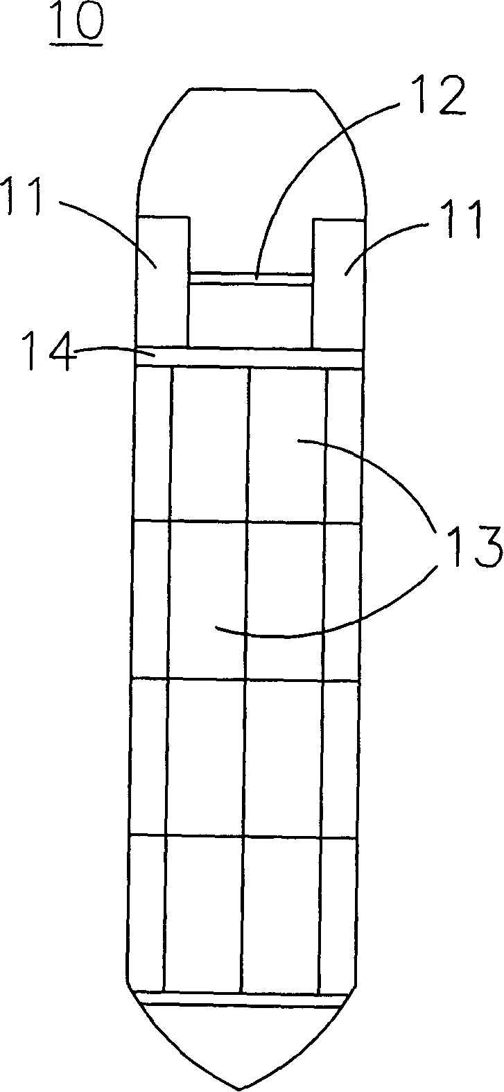
[0004] However, the fuel stored in this fuel tank structure is also used up when the voyage is completed, and fuel needs to be replenished again. If the price of crude oil soars, the cost of each voyage will also increase accordingly, thus increasing the operation cost on

Method used


Image

  • Oiltank structure
  • Oiltank structure
  • Oiltank structure

Examples


Embodiment Construction

[0027] In order to make the above-mentioned purposes, features, and advantages of the present invention more obvious and easy to understand, a preferred embodiment of the fuel tank structure according to the present invention is given below, and is described in detail as follows in conjunction with the accompanying drawings, wherein the same elements Description will be made with the same reference numerals.

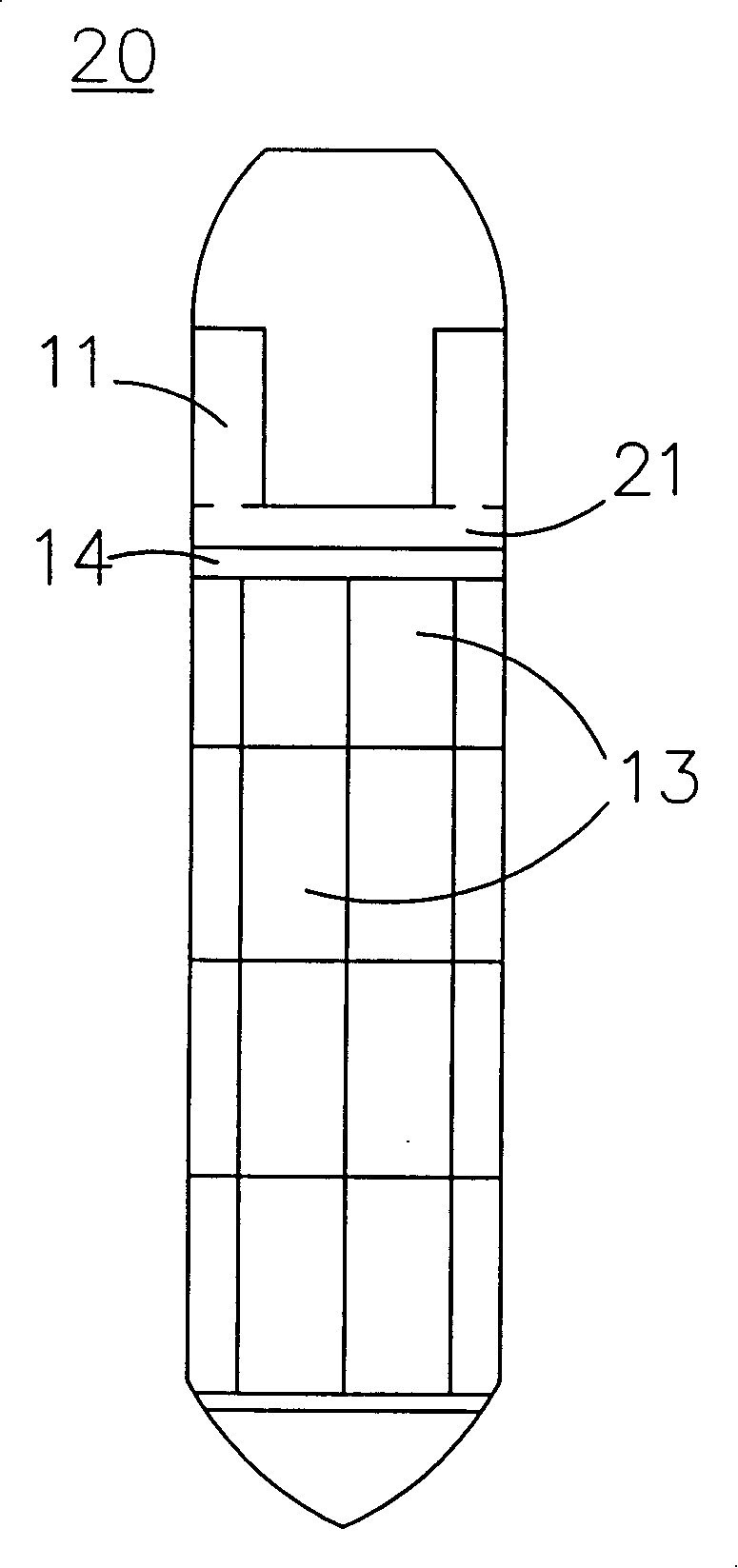
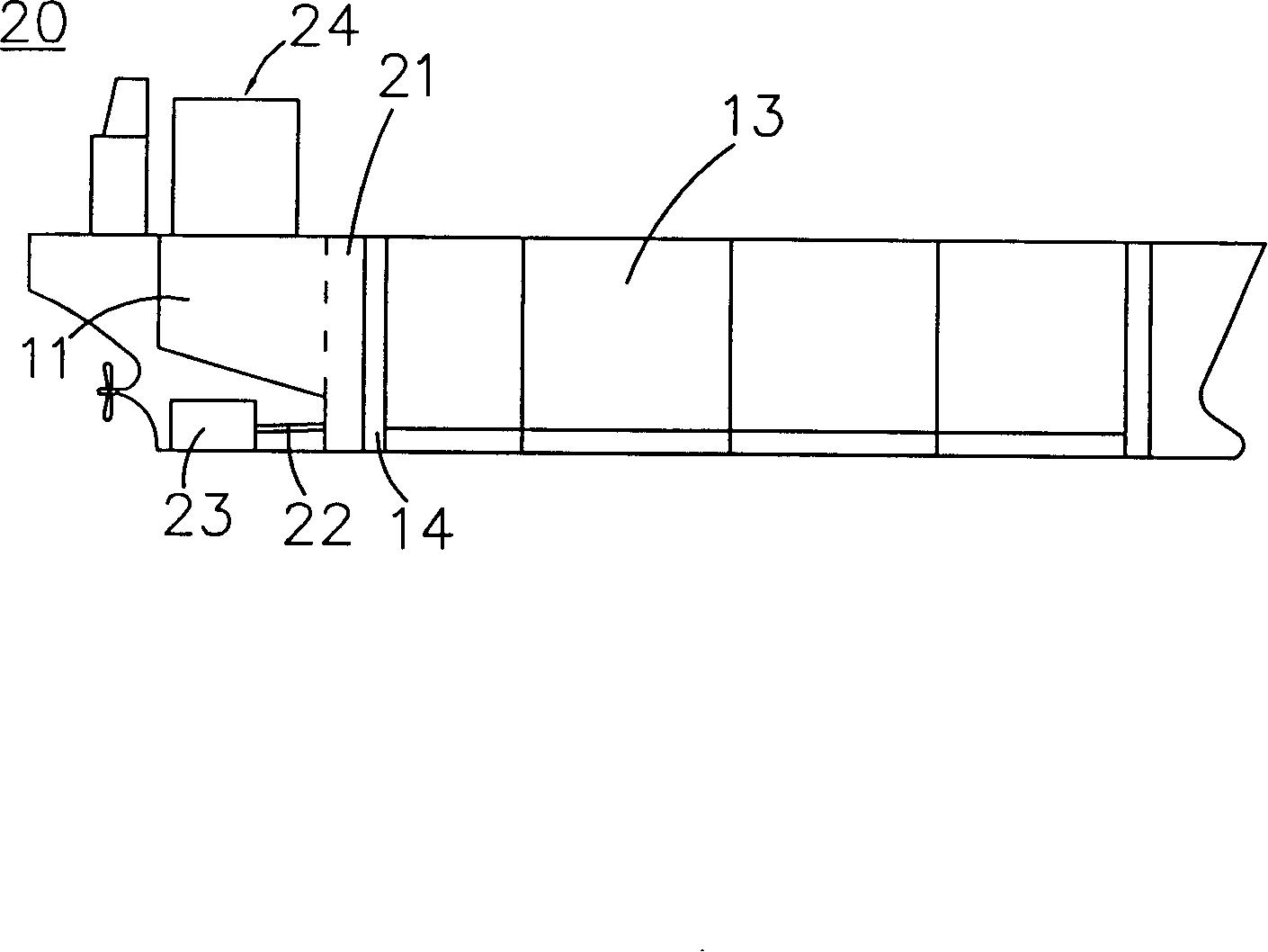
[0028] Please also refer to figure 2 and image 3 , figure 2 It is a schematic top view of a fuel tank structure of the present invention, image 3 It is a schematic side view of an oil tank structure of the present invention. In the figure, the fuel tank structure is suitable for a water vehicle 20. The water vehicle 20 is provided with a plurality of cargo tanks 13, a bridge 24 and two fuel tanks 11 located below the bridge 24, and the fuel tank structure includes a fuel tank 21 located on the cargo tank. Between the tank 13 and the fuel tanks 11 on both sides, t...


PUM


Abstract

The invention discloses a tank structure, applied to marine vehicle provided with complex number of cargo cabin grooves, bridge and tanks of two sides under the bridge. The said tank structure is composed of a tank between the cargo cabin groove and the tanks of two sides and the tank is connected with the tanks of two sides to make the loaded fuel communicated with each other. The said invention can make the loaded fuel communicated with each other, so that the communicating pipeline between the tanks of two sides can be saved up and the reserve fuel quantity of the marine vehicle can be increased.

Description

Technical field: [0001] The invention relates to a fuel tank, in particular to a fuel tank of a water vehicle and related to adding an oil storage tank to increase the oil storage capacity of the water vehicle. Background technique: [0002] The modern design of oil tankers is to provide a double hull design in the area of ​​the oil cargo storage tank. In this design, an oil-tight compartment is provided between the hull of a ship and an oil-tight bulkhead. The wall acts in effect as the inner hull of a ship. This compartment is designed to be provided as an empty space or to fill the space with ballast water. Furthermore, the oil tanks for storing fuel oil in ships are usually arranged immediately adjacent to the engine room and at a relatively high position in the ship. This area of ​​the ship tends to be crowded. If the ship is built with double hulls, the available space will be further reduced. small, or the overall size of the vessel would increase, causing considera...

Claims


Application Information

Patent Timeline
Patent Type & Authority Applications(China)
IPC IPC(8): B63B11/04
CPCB63B11/02B63B3/62B63B11/04
Inventor 苏信吉
Owner TAWWAN MARITIME TRANSPORTATION
Learn More