Amplifying circuit with pull-up and pull-down circuit to increase turning rate
A technique for amplifying circuits and circuits, which is applied to DC-coupled DC amplifiers, differential amplifiers, instruments, etc., and can solve problems such as poor efficiency, slow slew rate, and small slew rate
- Summary
- Abstract
- Description
- Claims
- Application Information
AI Technical Summary
Problems solved by technology
Method used
Image
Examples
Embodiment Construction
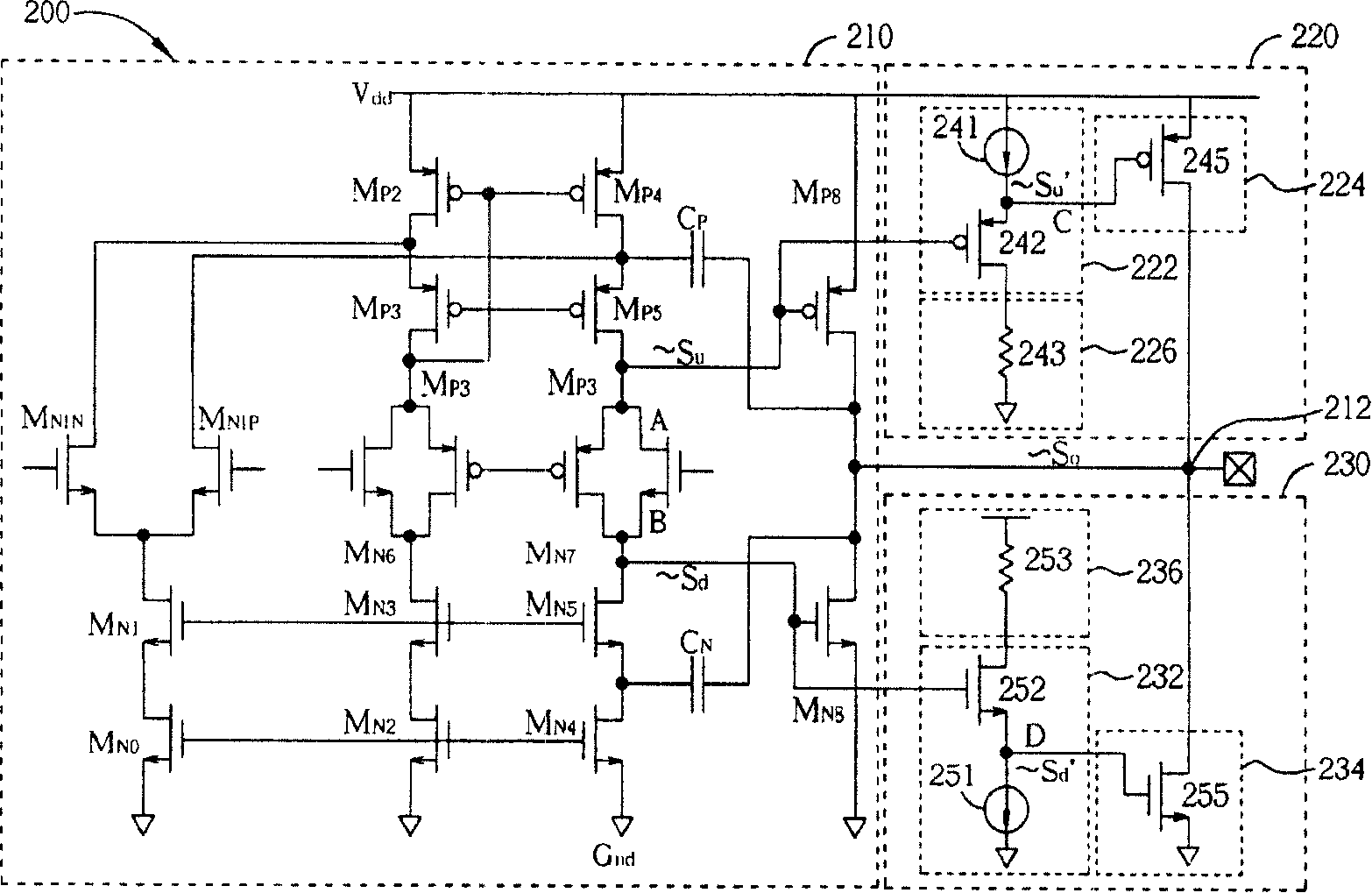
[0014] see figure 2 , figure 2 It is a schematic circuit diagram of the first embodiment of the amplification circuit 200 of the present invention. Such as figure 2 As shown, the amplifying circuit 200 includes an amplifier 210 , a pull-up circuit 220 and a pull-down circuit 230 . The amplifier 210 generates the first pull-up control signal S according to the input signal received by the input terminal. u , the first pull-down control signal S d And generate an output signal S at the output terminal 212 o , where the pull-up control signal S u and the pull-down control signal S d are equal to the output signal S o invert. The pull-up circuit 220 includes a first control module 222, a first adjustment module 224 and a first impedance unit 226, wherein the first control module 222 is coupled to the amplifier 210 for receiving the first pull-up control signal S u , and according to the first pull-up control signal S u Output the second pull-up control signal S u ’, ...
PUM
 Abstract
Description
Claims
Application Information
 - R&D
- Intellectual Property
- Life Sciences
- Materials
- Tech Scout
- Unparalleled Data Quality
- Higher Quality Content
- 60% Fewer Hallucinations
Browse by: Latest US Patents, China's latest patents, Technical Efficacy Thesaurus, Application Domain, Technology Topic, Popular Technical Reports.
© 2025 PatSnap. All rights reserved.Legal|Privacy policy|Modern Slavery Act Transparency Statement|Sitemap|About US| Contact US: help@patsnap.com


