Low-power consumption driven PWM regulation circuit

A technology of driving circuits and driving pulses, which is applied to electric light sources, electrical components, lighting devices, etc., to achieve the effect of reducing switching loss

Active Publication Date: 2013-03-27
SHANGHAI MUNICIPAL ELECTRIC POWER CO +2
View PDF2 Cites 0 Cited by
  • Summary
  • Abstract
  • Description
  • Claims
  • Application Information

AI Technical Summary

Problems solved by technology

Due to the storage effect of the transistor base area, the turn-off time is delayed; the collector junction capacitance makes the output pulse current have a bad influence on the input terminal; especially the pulse transformer in the input circuit, when the half-bridge inverter circuit is working, the switching current is in the Ringing occurs in the primary winding, and the combined force of its positive peak value and the positive charge stored in the base area causes the switching tube to be delayed to turn off, or to be repeatedly turned on, which causes "common state conduction". If it is hot, it will enter the second breakdown when it is turned on, and any protection circuit will be powerless against it.

Method used


Image

  • Low-power consumption driven PWM regulation circuit

Examples


Embodiment Construction

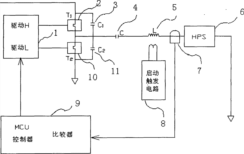
[0011] Below in conjunction with specific embodiment, further illustrate the present invention. It should be understood that these examples are only used to illustrate the present invention and are not intended to limit the scope of the present invention. In addition, it should be understood that after reading the teachings of the present invention, those skilled in the art can make various changes or modifications to the present invention, and these equivalent forms also fall within the scope defined by the appended claims of the present application. Such as figure 1 The schematic block diagram of the low-loss driving PWM regulation circuit shown in the figure shows that the driving circuit 1 of the half-bridge adopts an independently controllable driving chip; the working sequence of the driving chip is directly controlled by the single-chip MCU controller 9 . The drive circuit 1 of the half-bridge generates two independent high and low drive signals H, L, and the output o...


PUM


Abstract

The invention relates to a low-loss regulator circuit for driving the PWM; the invention comprises an LC oscillatory circuit consisting of a driving circuit, a capacitance C and a inductance L which are connected in series, a switch tube T1, a switch tube T2, a capacitance C1, a capacitance C2, an MCU controller and a current sampling magnetic ring; the MCU controller regulates the opening and closing sequence according to the working frequency and the switch tube can reduce the current loss in the opening and closing process. The invention overcomes the defect that the switch tube of the present electronic ballast is great and the temperature rises greatly. The invention changes the state that the working frequency of the present electronic ballast is basically unchanged from the beginning to the end; with the invention, the opening and closing sequence and working frequency are changing in the process of the different operational stages according to the light features.

Description

technical field [0001] The invention relates to a regulating circuit, in particular to a driving regulating circuit for high-pressure sodium lamps and metal halide lamps. Background technique [0002] The rise of the green lighting industry in the world makes electronic ballasts popular. Relevant enterprises have all spotted the huge business opportunities hidden in electronic ballasts. In particular, the energy-saving potential hidden in the high-pressure sodium lamp is more concerned by everyone. The high-pressure sodium lamp (HPS lamp) is a high-intensity gas discharge lamp (HID lamp) with excellent performance. Its advantages are high luminous efficiency, long life, and good light color. , so it is widely used. According to statistics, if all high-pressure gas discharge lamps in the country are replaced with electronic ballasts, 24.6 billion kWh of electricity can be saved throughout the year, which can solve the current 1 / 3 of the country's electricity shortage. The...

Claims


Application Information

Patent Timeline
Patent Type & Authority Patents(China)
IPC IPC(8): H05B41/292H05B41/02
Inventor 叶传良宋若槑
Owner SHANGHAI MUNICIPAL ELECTRIC POWER CO
Why Eureka
Try Eureka