Radiographic imaging apparatus, imaging unit and radiographic imaging system

A technology of an imaging unit and imaging equipment, which is applied in photography, instruments for radiological diagnosis, material analysis using radiation, etc., and can solve problems such as the fall of the wrong X-ray detection unit 17

Inactive Publication Date: 2008-04-23
CANON KK
View PDF1 Cites 8 Cited by
  • Summary
  • Abstract
  • Description
  • Claims
  • Application Information

AI Technical Summary

Problems solved by technology

[0009] However, if the detachment direction of the X-ray detection unit 17 coincides with the direction of g...

Method used


Image

  • Radiographic imaging apparatus, imaging unit and radiographic imaging system
  • Radiographic imaging apparatus, imaging unit and radiographic imaging system
  • Radiographic imaging apparatus, imaging unit and radiographic imaging system

Examples


Embodiment Construction

[0023] Embodiments of the present invention will be described in detail with reference to FIGS. 1 to 6 . The radiation includes, for example, electromagnetic waves such as X-rays, α-rays, β-rays, and γ-rays. The radiographic apparatus according to various embodiments can be applied to the radiographic system shown in FIG. 7 .

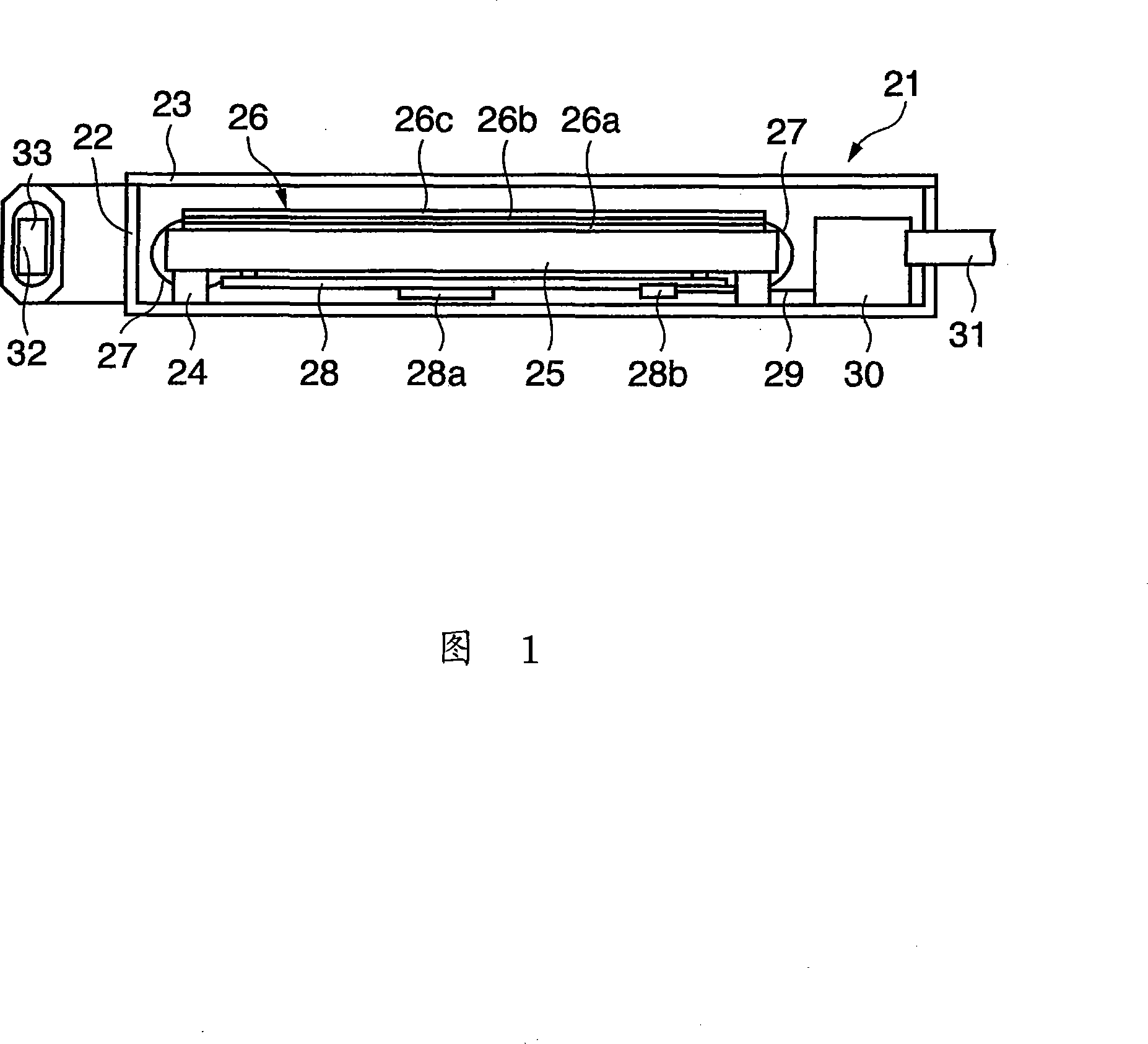
[0024] FIG. 1 is a sectional view of an imaging unit 21 according to the first embodiment. A case cover 23 made of a radiolucent material seals the upwardly open box-shaped case 22 . A base 25 made of metal is fixed in the case 22 via a supporting unit 24 . An X-ray image detection panel 26 formed by stacking a substrate 26 a , a photoelectric conversion element 26 b , and a fluorescent plate 26 c is arranged on the base 25 .

[0025] A glass plate is often used as the substrate 26a because it does not chemically react with semiconductor elements, is resistant to temperatures during semiconductor processing, and has dimensional stability. The photoe...


PUM


Abstract

The present invention provides a radiographic apparatus, an imaging unit, and a radiographic system. The radiographic apparatus includes: a holding unit that detachably holds an imaging unit for detecting radiation generated by a radiation generating unit and acquiring a radiographic image; a restricting unit that restricts detachment of the imaging unit from the holding unit; and a controller that releases the restriction of the detachment restricting unit when the grip detection unit for detecting gripping of the imaging unit detects the gripping on the imaging unit.

Description

technical field [0001] The present invention relates to a radiographic apparatus, an imaging unit, and a radiographic system. Background technique [0002] Advances in digital technology in recent years have led to the increasing popularity of radiographic equipment that converts radiographic images into electrical signals, processes the electrical signals, and reproduces them as visible images on, for example, a CRT, thereby obtaining high-quality ray images. [0003] Fig. 7 is a conceptual diagram of a radiographic system using the radiographic apparatus described above. A radiographic apparatus 1 arranged in front of a subject P includes a radiation detection sensor 2 . The ray generator 3 arranged behind the subject P generates rays and irradiates the subject P with the rays. The phosphor passing through the radiation detection sensor 2 converts the radiation transmitted through the subject P into visible light. The photoelectric conversion elements arranged in a two...

Claims


Application Information

Patent Timeline
IPC IPC(8): A61B6/00G01N23/04G03B42/02
CPCA61B6/4441A61B6/4405
Inventor 渡部哲绪
Owner CANON KK
Why Eureka
Try Eureka