
Method for controlling a powder sprayer

A duster and control device technology, applied in the field of duster, can solve the problems of printing quality reduction, achieve high printing quality and avoid adverse effects

Active Publication Date: 2013-06-05
海德堡印刷机械知识产权股份两合公司
View PDF3 Cites 0 Cited by
  • Summary
  • Abstract
  • Description
  • Claims
  • Application Information

AI Technical Summary

Problems solved by technology

As a result, the printing quality is significantly reduced

Method used


Image

  • Method for controlling a powder sprayer
  • Method for controlling a powder sprayer

Examples


Embodiment Construction

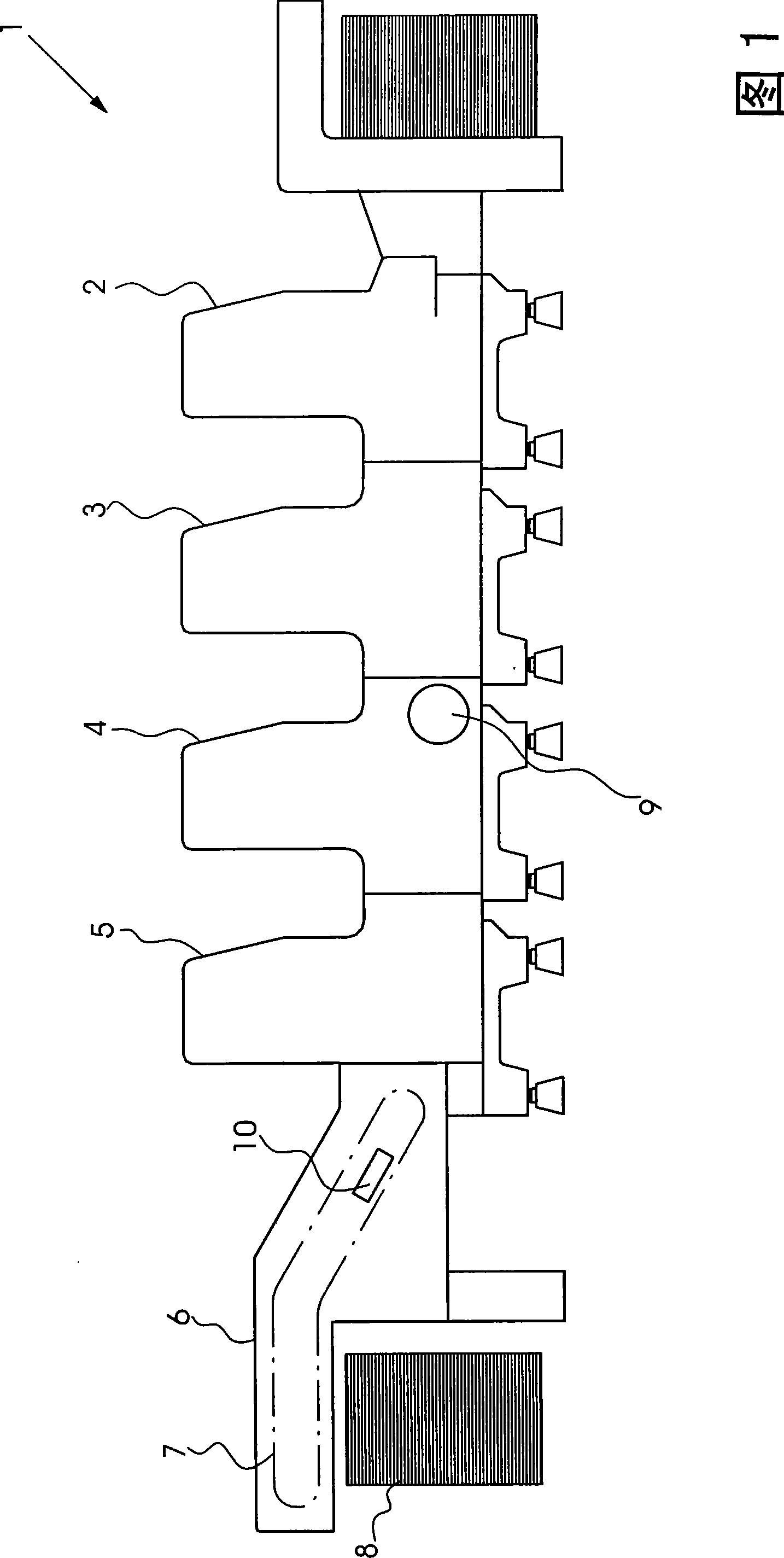
[0020] figure 1 A printing press 1 with printing units 2 to 5 and a delivery 6 is shown in . The delivery includes a chain conveyor 7 which deposits the printed sheets onto a delivery pile 8 . Furthermore, the printing press includes an inverting unit 9, which can be switched from a pure front printing mode to a perfect printing mode. In the pure front printing mode without turning over the sheets, the printed pages are printed not only in the printing units 2 and 3 arranged in front of the turning unit 9 but also in the printing units 4 and 5 arranged behind the turning unit 9 sheet for front printing. In perfecting mode, the front side of the printed sheet is printed in the upstream printing units 2 and 3 and the reverse side is printed in the downstream printing units 4 and 5 . A duster 10 is arranged in the delivery 6 , which dusts the printed sheets conveyed by the chain conveyor 7 .

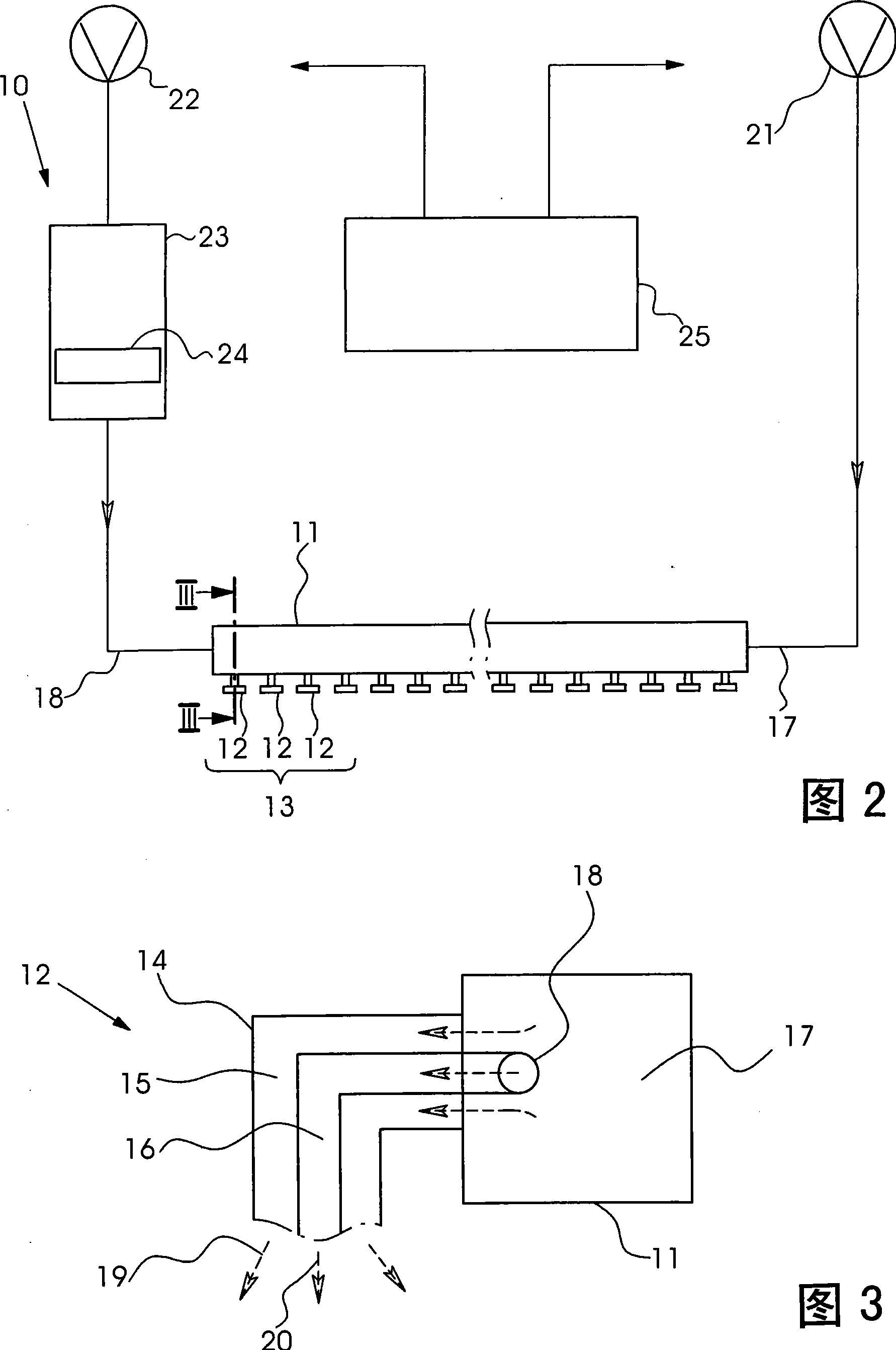
[0021] figure 2 It is shown that the duster comprises a nozzle bar 11 with sleeve...


PUM


Abstract

The method involves controlling a mantle-stream nozzle arrangement (13) using a control unit (25) based on operating parameters of a printing machine, where the parameters are different printed sheet-grammages. The parameters are adjusted in a face- and reverse printing mode and in a clear face-sided printing mode. Dispensing speed of mantle streams of the arrangement is changed based on the parameters. Dispensing speed of power air-core streams of the arrangement is maintained invariably during the change of the dispensing speed of the mantle streams.

Description

technical field [0001] The invention relates to a method for controlling a duster with a sleeve nozzle arrangement in a printing press. Background technique [0002] A duster with a sleeve nozzle arrangement is described in DE 10001590 A1. The nozzle heads are arranged in a row in this duster. Each nozzle head has two nozzles, from which a jet of powder air is ejected each. A blowpipe is arranged above the nozzle head, from which a jet of compressed air emerges. The delivery velocity of the compressed air jet is approximately twice the delivery velocity of the powder air jet. These compressed air jets together form a powder-free support air jacket flow which surrounds the powder air jet on all sides. The supporting air sleeve flow shields the powder air jet from the eddy currents caused by the movement of the grippers transporting the printed sheets. This ensures that the powder air jet is applied to the printed sheet without being affected by turbulence. However, the ...

Claims


Application Information

Patent Timeline
Patent Type & Authority Patents(China)
IPC IPC(8): B41F23/06B05B7/14
CPCB05B1/202B41F23/06B05B7/1404B05B7/1486
Inventor P·T·布拉泽C·哈斯M·施特尔特
Owner 海德堡印刷机械知识产权股份两合公司
Learn More