Eureka AIR delivers breakthrough ideas for toughest innovation challenges, trusted by R&D personnel around the world.

Railway sleeper

A sleeper and track technology, applied in the field of track sleepers, can solve the problem that the attenuation of mechanical vibration is not completely satisfactory

Inactive Publication Date: 2008-04-23
ALSTOM TRANSPORT SA
View PDF2 Cites 14 Cited by
  • Summary
  • Abstract
  • Description
  • Claims
  • Application Information

AI Technical Summary

Problems solved by technology

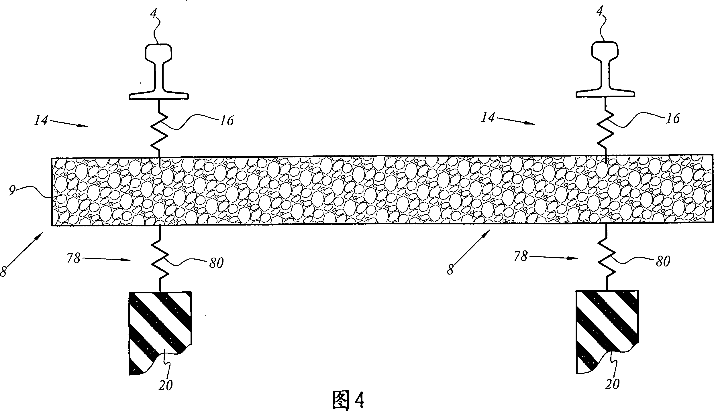
[0010] [10] However, the currently known attenuation of mechanical vibrations when a train passes over such a track system is not entirely satisfactory.

Method used


Image

  • Railway sleeper
  • Railway sleeper
  • Railway sleeper

Examples


Embodiment Construction

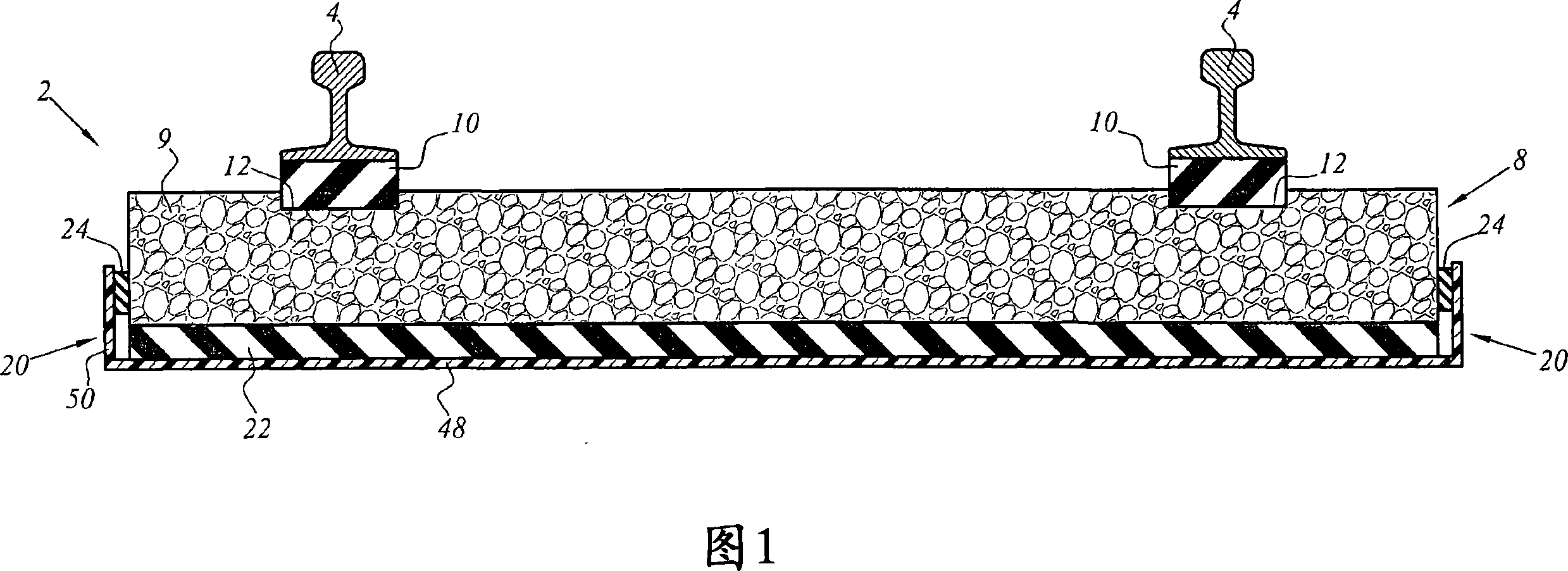
[0030] [30] The track section 2 in the first embodiment of the present invention is schematically shown in FIG. 1 . The track section 2 comprises two longitudinal rails 4 fastened to sleepers 8 . The sleeper 8 comprises a single concrete block 9 and two elastic support elements 10 arranged between each track 4 and the concrete block 9 .

[0031] [31] By convention, the longitudinal rail 4 is determined to be used as a reference for the longitudinal direction.

[0032] [32] The elastic support element 10 is substantially in the form of a cuboid. In the embodiment shown in FIG. 1 , their width is substantially equal to the width of the base of the track 4 and their length is substantially equal to the width of the block 9 .

[0033] [33] The elastic support elements 10 are received in respective grooves 12 in the block 9 . The profile of each groove 12 in the sectional view is substantially rectangular. The width and length of each groove 12 are substantially equal to the co...


PUM


Abstract

The rail track tie including: a rigid block presenting a bottom face, and a top face for receiving at least one longitudinal rail; a cover for receiving the rigid block and in the form of a rigid shell including a bottom and a peripheral rim around the bottom; and a resilient soleplate disposed between the bottom face of the rigid block and the bottom of the cover. The resilient soleplate has dynamic stiffness k2 lying in the range of 6 kN / mm to 10 kN / mm, and preferably in the range of 6 kN / mm to 8 kN / mm.

Description

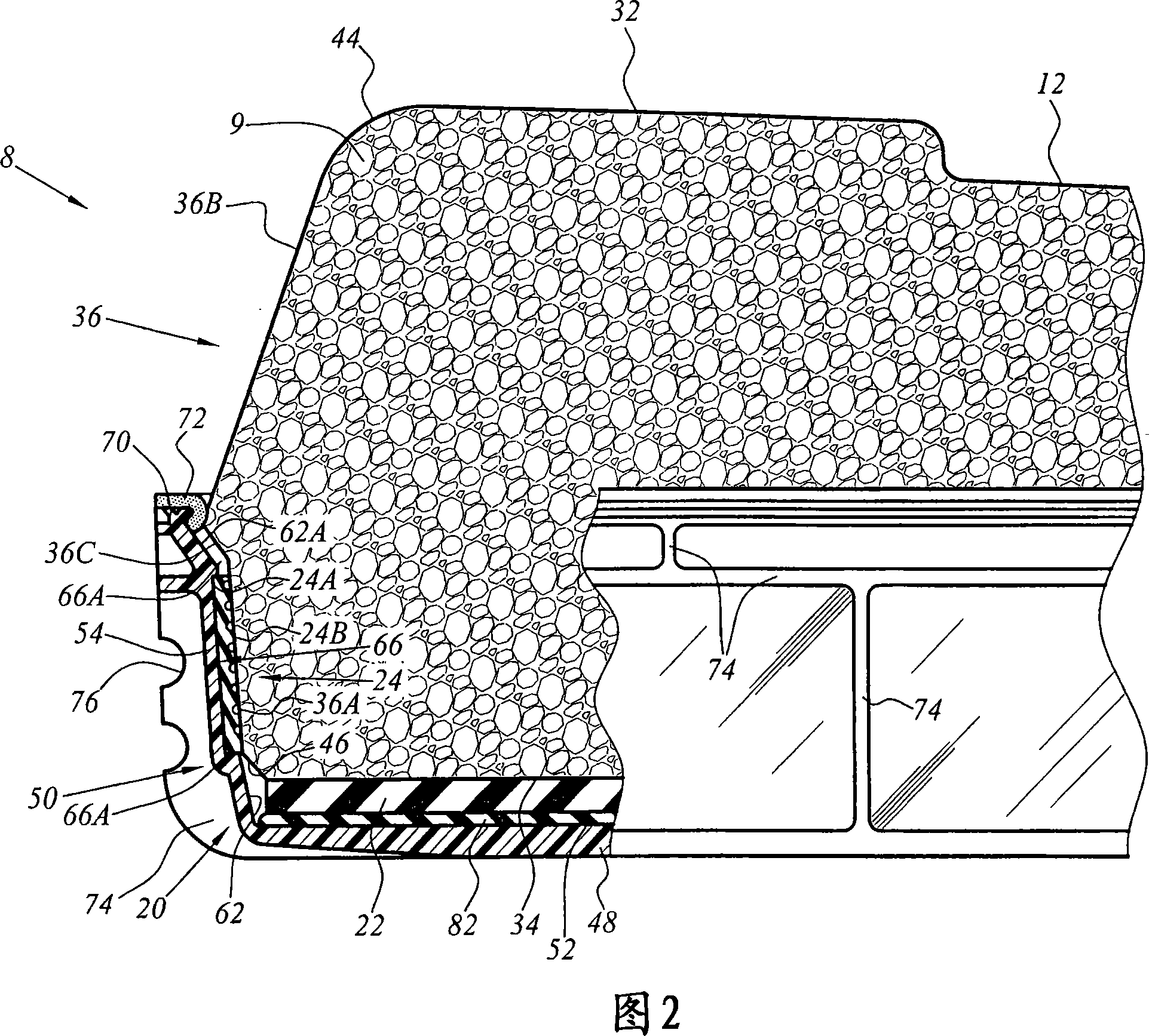
technical field [0001] [01] The present invention relates to a rail sleeper (also known as a "sleeper"), a type of rail sleeper comprising: [0002] [02] - a rigid block having a bottom surface and a top surface for receiving at least one longitudinal rail; [0003] [03] - A casing for receiving said rigid mass, in the form of a rigid shell comprising a base and a perimeter frame surrounding said base; and [0004] [04] - An elastic backing plate arranged between the bottom surface of said rigid block and the bottom of said casing. Background technique [0005] [05] Such sleepers are often used for laying tracks without ballast, for example in or on structures such as tunnels or viaducts, where the sleepers are supported by roadbeds or slabs. [0006] [06] EP-A-0 919 666 describes a sleeper of this type. The rigid casing is embedded in the concrete slab and together with it forms a rigid unit. [0007] [07] Each track typically rests on elastic support elements arranged ...

Claims


Application Information

Patent Timeline
Patent Type & Authority Applications(China)
IPC IPC(8): E01B3/00
CPCE01B3/44E01B3/40E01B1/005E01B9/68E01B2204/01
Inventor M·吉拉尔迪C·珀蒂F·勒科尔I·罗伯特森
Owner ALSTOM TRANSPORT SA
Why Eureka
Eureka Blog
Learn More