Method and device for testing dynamic stiffness of high-speed main shaft

A technology of high-speed spindle and test method, applied in the direction of mechanical bearing testing, etc., can solve the problems of prone to friction, low rigidity of air bearing, non-uniform spindle cross-section, etc., to reduce heat generation and wear, small rolling friction coefficient, Simple and compact structure

Inactive Publication Date: 2011-11-23
HUNAN UNIV
View PDF5 Cites 25 Cited by
  • Summary
  • Abstract
  • Description
  • Claims
  • Application Information

AI Technical Summary

Problems solved by technology

[0005]1. The electromagnetic loading measuring device has the disadvantage that the electromagnetic loading device is complicated and occupies a large space. Spindle detection for special experiments is more effective and difficult to use universally
Its disadvantages are as follows: a. The rigidity of the air bearing is small, and the loading force is limited; b. The air bearing measuring device takes up a lot of space, which is restricted by the space at the extension end of the spindle; c. It is difficult to maintain the air pressure during the loading process. In the floating state, it is easy to cause the bearing and the main shaft to collide due to the bias of the load.
[0007]3. Non-contact liquid suspension loading type measuring device, its loading capacity

Method used


Image

  • Method and device for testing dynamic stiffness of high-speed main shaft
  • Method and device for testing dynamic stiffness of high-speed main shaft
  • Method and device for testing dynamic stiffness of high-speed main shaft

Examples


Embodiment Construction

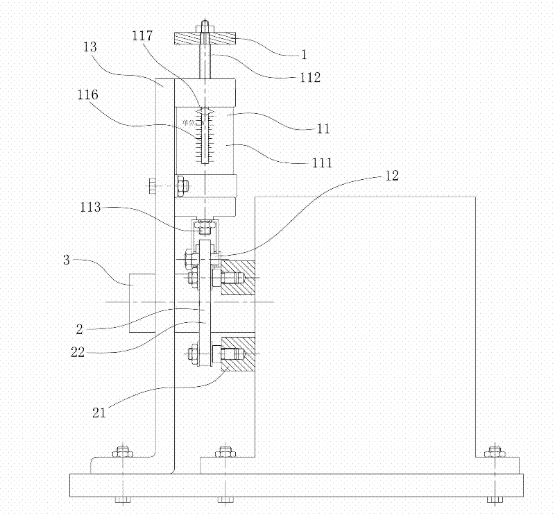
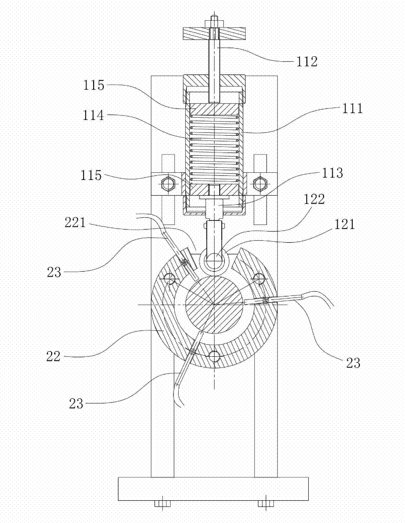
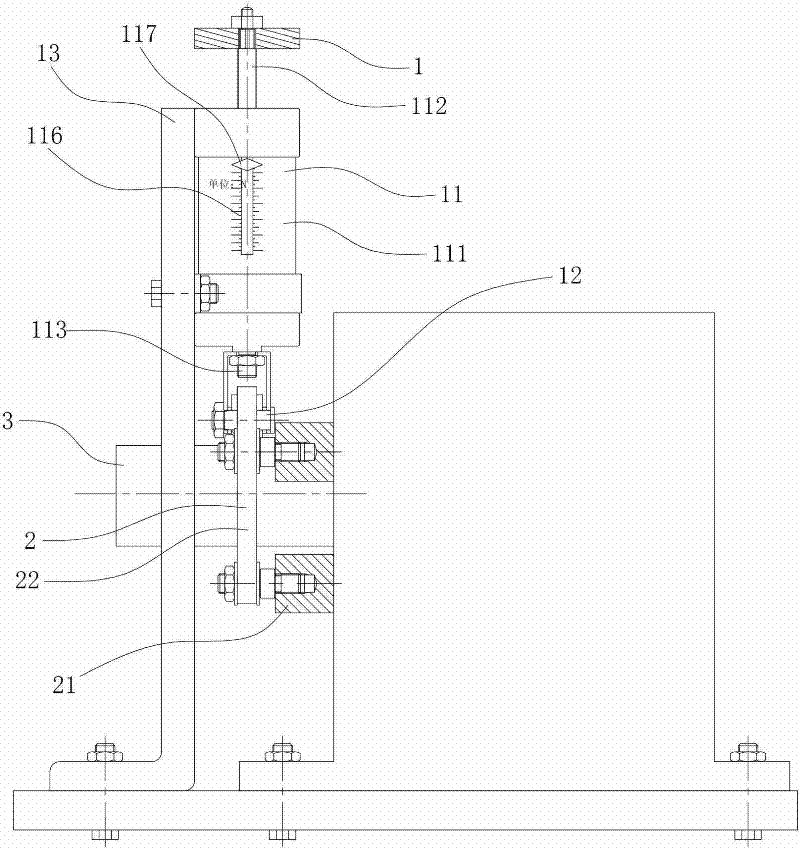
[0030] This embodiment provides a method for testing the dynamic stiffness of a high-speed main shaft, which includes a step of radial loading, a step of measuring the displacement of the shaft center, and a step of calculating the dynamic stiffness value, such as figure 1 and figure 2 As shown, when carrying out the radial loading step, the loading element 11 with a readable loading force pushes a rotatable rolling member 12 to contact the circumferential surface of the tested high-speed spindle 3, and makes the direction of the loading force point to the tested high-speed spindle 3 When the tested high-speed main shaft 3 rotates, the rolling element 12 rotates synchronously under the friction force provided by the circumferential surface. The wear of the component 12 is small, which can effectively avoid the heat and wear caused by the traditional loading method, and at the same time has little impact on the measurement accuracy; the loading force can be obtained by reading...


PUM


Abstract

The invention relates to a method for testing dynamic stiffness of a high-speed main shaft, which is high in testing precision and convenient to operate. The method comprises the radial loading step, the shaft center displacement measuring step and the dynamic stiffness value calculating step, when the radial loading step is performed, a readable loading element is used for pushing a rolling part to be in contact with the tested high-speed main shaft and enabling the direction of loading force to point to the shaft center of the tested high-speed main shaft, and the rolling part performs synchronous autorotation under the action of frictional force during the rotation of the tested high-speed main shaft. A device for testing the dynamic stiffness of the high-speed main shaft, which is simple in structure, small in occupied space, low in cost and high in precision, comprises a radial loading device and a shaft center displacement measuring device, wherein the radial loading device comprises the readable loading element, the rolling part and a fixed frame of the loading element, the loading element is fixed on the fixed frame of the loading element, the rolling part capable of performing the autorotation is assembled at the output end of the loading element, the rolling part is further in contact with the circumferential surface of the tested high-speed main shaft and the direction of the loading force of the loading element points to the shaft center of the tested high-speed main shaft.

Description

technical field [0001] The invention relates to a spindle dynamic stiffness testing technology, in particular to a high-speed spindle dynamic stiffness testing method and device. Background technique [0002] The high-speed spindle is the core functional component of modern machine tools. Its function is to drive the tool (grinding wheel) or workpiece to rotate to achieve high-speed precision machining. With the continuous improvement of modern industry's requirements for machining accuracy and machining efficiency of machine tools, machine tools have higher and higher requirements for spindle performance. [0003] Rigidity is one of the important indicators to measure the performance of high-speed spindle. Spindle stiffness includes static stiffness at rest and dynamic stiffness at high speed. The currently feasible and widely used stiffness testing method in engineering is the static stiffness testing method. However, the static stiffness cannot truly reflect the abilit...

Claims


Application Information

Patent Timeline
IPC IPC(8): G01M13/04
Inventor 熊万里李想侯志泉吕浪吕冰海
Owner HUNAN UNIV
Why Eureka
Try Eureka