Oil film lubrication method between large-end face of taperroller and capped edge of housing washer in thrush bearing

A thrust bearing, oil film lubrication technology, applied in the direction of bearing components, shafts and bearings, mechanical equipment, etc., can solve problems such as increased power consumption, reduced support capacity, affected normal operation, etc., to reduce frictional power consumption, improve mechanism performance, The effect of perfecting the design method

Inactive Publication Date: 2007-12-26
郭溪泉
View PDF0 Cites 6 Cited by
  • Summary
  • Abstract
  • Description
  • Claims
  • Application Information

AI Technical Summary

Problems solved by technology

Taking petroleum drilling equipment as an example, the thrust bearing of the faucet (or the thrust bearing of the hook) is the most critical working part of the equipment. Because it works under harsh conditions such as poor environment, heavy load, continuous operation, and difficulty in assembly and disassembly, the It is prone to failure or failure and at the same time will cause a great loss in production
On-site statistical data show that the main reason for the failure or failure of this type of bearing is that the large end of the tapered roller "gnaws the edge", that is, the large end of the tapered roller faces the grinding of the inner surface of the rib of the bearing race, or the The upper edge of the rib scrapes the large end face of the cone roller, or both, resulting in internal wear of the bearing, increased rotational resistance torque, heat generation, and increased power consumption, which affects normal operation and eventually leads to failure
[0003] Although this problem has long attracted the great attention of the rolling bearing industry (including design, manufacturing, research and other departments), the work carried out is all from reducing surface roughness, improving wear resistance, and performing elastohydrodynamic lubrication (or thin film) Lubrication) theoretical analysis and other aspects, but only achieved "knowledge" and "treatment of the symptoms", but could not solve the problem fundamentally
Today, friction, wear, heat, load and speed, reliability, and life of this type of bearing still exist, which limit the performance of this type of bearing and affect the application of this type of bearing. It also reduces its ability to support the development of the applied industry

Method used


Image

  • Oil film lubrication method between large-end face of taperroller and capped edge of housing washer in thrush bearing
  • Oil film lubrication method between large-end face of taperroller and capped edge of housing washer in thrush bearing
  • Oil film lubrication method between large-end face of taperroller and capped edge of housing washer in thrush bearing

Examples


Embodiment Construction

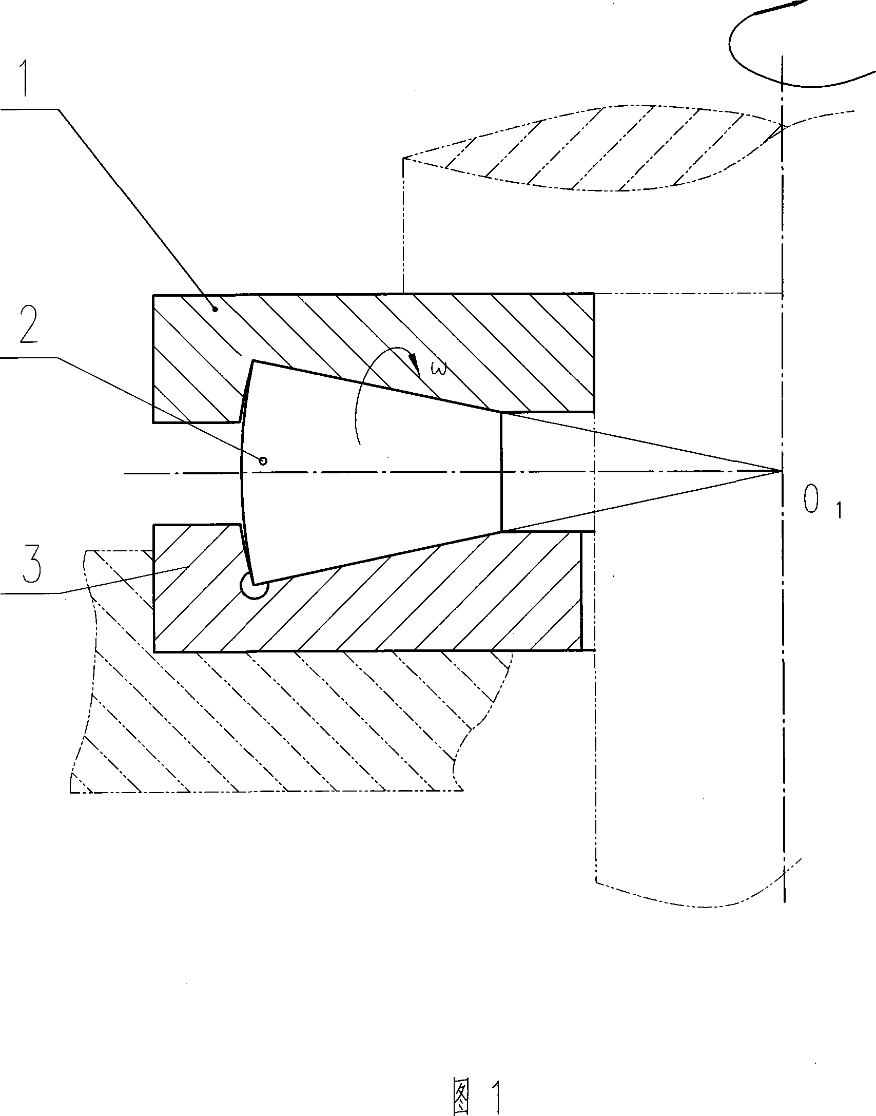
[0040]As shown in Figure 1, the structure of the tapered roller thrust bearing is that the rolling elements - tapered rollers 2 are arranged between the shaft ring 1 and the seat ring 3, and the tapered rollers are arranged equidistantly by the cage (not shown in the figure). show). The design and manufacture of the shaft ring, seat ring and tapered roller, that is, the raceway and rib, are exactly the same for the shaft ring and seat ring.

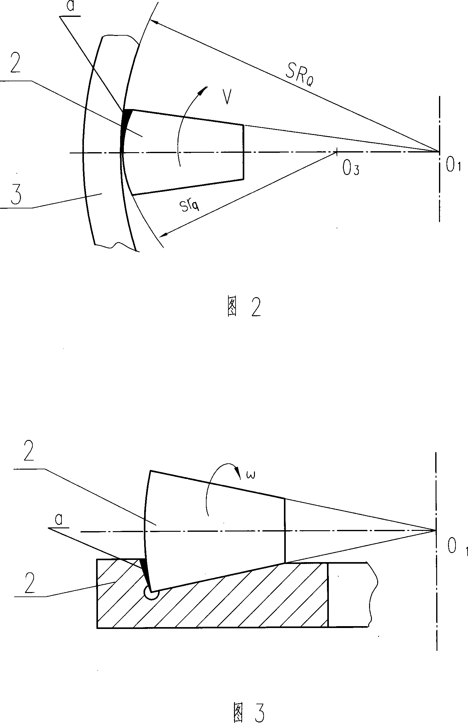
[0041] As shown in Figure 2, an oil film lubrication method for the large end surface of the thrust bearing tapered roller and the rib of the seat ring. ), a wedge-shaped gap with a large front and a small rear is formed between the front part of the large end face of the tapered roll and the inner wall of the seat ring rib, as indicated by "a" in the figure (that is, a convergent gap with a dynamic pressure effect. Wedge-shaped gap), like a water ski with a tilted front end, as long as it moves forward, it will generate buoyancy. The "...


PUM


Abstract

This invention discloses a film lubrication method for thrust bearing roller cone races and ribs, which forms a wedge clearance between the large end surface of a roller and inside wall of a ring rib and fills it with lubrication oil, when the shape, size of the clearance and axial load, glide speed and viscosity of the oil are matched to each other, a dynamic pressure film is formed between the two surfaces, in which the wedge clearance is formed by cone roller spherical large end surface and the ring rib spherical ring, so it's easy to form a dynamic pressure film by selecting race SRQ of the inner surface of the race and axis ring and srq of the cone large end surface reasonably.

Description

technical field [0001] The invention belongs to a rolling bearing of a mechanical transmission device, and relates to a design method for changing the frictional properties of the loaded sliding part of the rolling bearing and forming dynamic pressure oil film lubrication (or thick film lubrication) to improve transmission efficiency and reliability; The breakthrough and improvement of transmission design ideas and methods. Background technique [0002] Thrust tapered roller bearings bear axial load; it consists of two flat rings, tapered rollers and a cage; the flat ring matching the seat is called the seat ring, and the flat ring matching the shaft is called the shaft ring. The middle one is the rolling element-tapered roller (hereinafter referred to as "tapered roller"), and the cage is to make the arrangement of the tapered rollers in an orderly manner; the seat ring and the shaft ring are just one stationary and the other rotating, and their structure and force factor ...

Claims


Application Information

Patent Timeline
Patent Type & Authority Applications(China)
IPC IPC(8): F16C33/66
Inventor 郭溪泉郭逾吴国华肖永刚郭李艳郭李婷
Owner 郭溪泉
Why Eureka
Try Eureka