Method for separating different virtual LAN services

A virtual local area network and business technology, applied in the field of network communication, to achieve the effect of ensuring isolation and realizing transparent processing

Inactive Publication Date: 2008-04-23
HUAWEI TECH CO LTD
View PDF0 Cites 23 Cited by
  • Summary
  • Abstract
  • Description
  • Claims
  • Application Information

AI Technical Summary

Problems solved by technology

This method does not provide a configuration method for the multicast address forwarding table for the shortest pa

Method used


Image

  • Method for separating different virtual LAN services
  • Method for separating different virtual LAN services
  • Method for separating different virtual LAN services

Examples


Embodiment 1

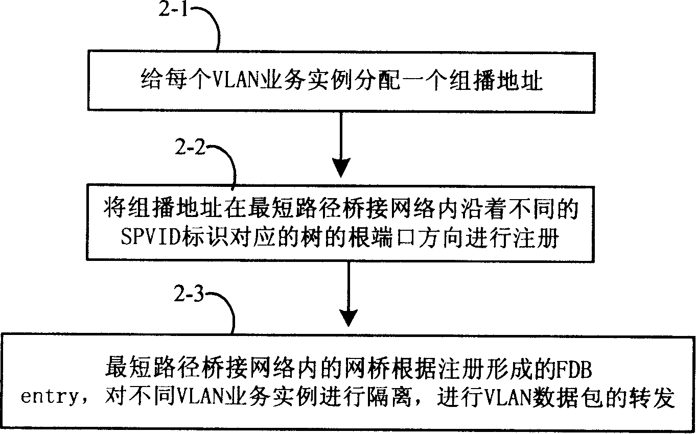
[0047] The specific processing flow of embodiment 1 is as figure 2 shown, including the following steps:

[0048] Step 2-1. Assign a multicast address to each VLAN service instance.

[0049] Embodiment 1 utilizes and expands the existing MMRP (Multi-Multicast Registration Protocol) technology. Firstly, a unique multicast address needs to be assigned to each accessed customer VLAN service instance in the shortest path bridging network as identification information of the VLAN service instance. The multicast address belongs to the MAC address space of the shortest path bridging network. The multicast address can be assigned before the ingress tree of the access bridge is generated, or after the ingress tree is generated.

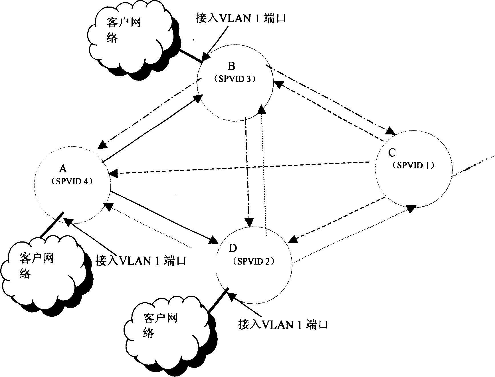
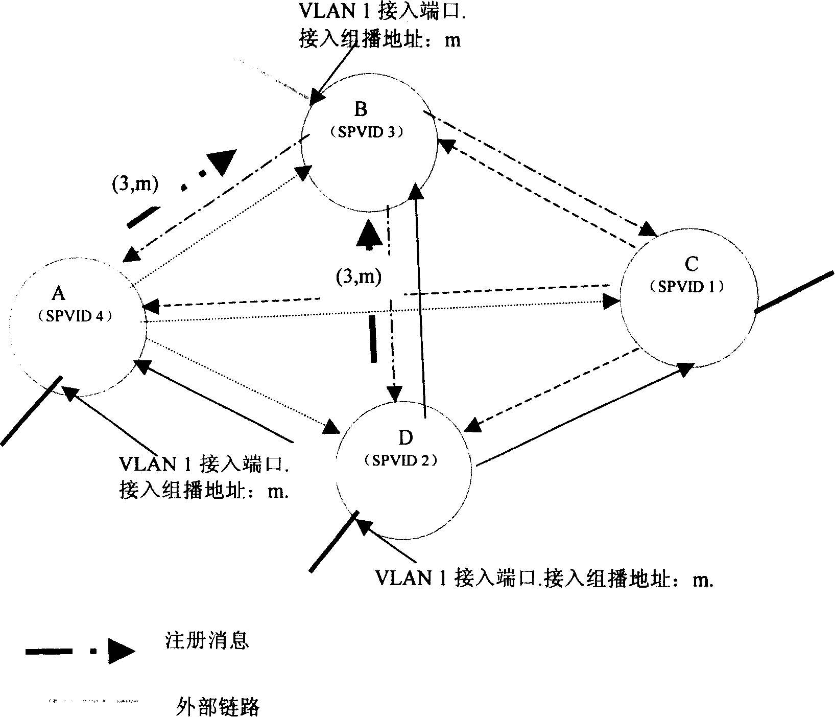
[0050] For example, in image 3 In the bridge network shown, a shortest path bridge network is composed of bridge nodes A, B, C, and D, and four entry trees are generated, which are represented by different line segments. Now there is a service instance ...

Embodiment 2

[0067] The core of Embodiment 2 is: use SPVID groups to isolate different VLAN service instances, and perform SPVID group registration along the direction of the root port of the spanning tree corresponding to different SPVID identifiers in the shortest path bridging network.

[0068] The specific processing flow of embodiment 2 is as Figure 4 shown, including the following steps:

[0069] Step 4-1, assign an SPVID group to each VLAN service instance, and form a translation table including the relationship between the VLAN ID and the SPVID group.

[0070]Firstly, each access bridge in the shortest path bridging network needs to allocate an SPVID corresponding to each accessed customer VLAN service as the identification information of the VLAN service instance. The SPVID is unique within the entire shortest path bridging network. Therefore, a group of SPVIDs (SPVIDs) is assigned to a VLAN service instance.

[0071] If different VLAN service instances are connected to the sa...


PUM


Abstract

The method includes following steps: assigning ID information for service instance connected to virtual local area network (VLAN) in bridge network with shortest path (BNSP); the said access bridge transfers the said ID information along direction of root ports of different entry trees in BNSP; based on the said ID information received along direction of root port of entry tree, the access bridge in BNSP identifies VLAN service instance. The method can insulate different VLAN services in BNSP so as to guarantee that VLAN service data packets are transmitted within VLAN area.

Description

technical field [0001] The invention relates to the field of network communication, in particular to a method for isolating different virtual local area network services. Background technique [0002] In a traditional network interconnected by Ethernet bridges, since the same and unique spanning tree is used for data forwarding in the same broadcast domain, it is usually not guaranteed that data packets are forwarded along the shortest path, resulting in data Packets are concentrated on certain links. [0003] In order to enable the bridge to forward data according to the shortest path, there are currently the International Standards Organization IEEE (Institute of Electrical and Electronics Engineers) Shortest Path Bridge Project Group and the International Standards Organization IETF (Internet Engineering Task Force) TRILL (Transparent Interconnection in Multiple Links). Even) working groups are conducting research according to two different methods. [0004] According t...

Claims


Application Information

Patent Timeline
IPC IPC(8): H04L12/46H04L12/66H04L29/06H04L12/56
CPCH04L45/48H04L12/4641H04L45/12H04L45/484
Inventor 杨发明管红光
Owner HUAWEI TECH CO LTD
Why Eureka
Try Eureka