
Fork type controlled non-contact wedge backstop

A non-contact, backstop technology, applied in the direction of brake type, conveyor control device, conveyor objects, etc., can solve the problems of uneven distribution of positioning pins and stop pins, strict assembly process requirements, inconvenient serial processing, etc. To achieve the effect of easy assembly, uniform load distribution and low cost

Inactive Publication Date: 2008-04-30
吕泽英
View PDF0 Cites 0 Cited by
  • Summary
  • Abstract
  • Description
  • Claims
  • Application Information

AI Technical Summary

Problems solved by technology

[0002] At present, contact or non-contact wedge backstops are generally used on belt conveyors, bucket elevators and other conveying equipment at home and abroad to prevent the equipment from being reversed due to the self-weight of the conveyed materials when the equipment is shut down, and to ensure that the equipment and personnel safety, especially the non-contact wedge backstop has been widely used; however, there are still some deficiencies in use: 1) Due to the uneven distribution of positioning pins and stop pins on the yoke plate and dial ring, The assembly process requirements of each component are strict, it is not convenient for serial processing, and the manufacturing cost is high; 2) Since the shift fork part protrudes from the circumference of the end cover to connect with the controller, most of the protruding parts are long holes, which is not easy to seal

Method used


Image

  • Fork type controlled non-contact wedge backstop
  • Fork type controlled non-contact wedge backstop
  • Fork type controlled non-contact wedge backstop

Examples


Embodiment 1

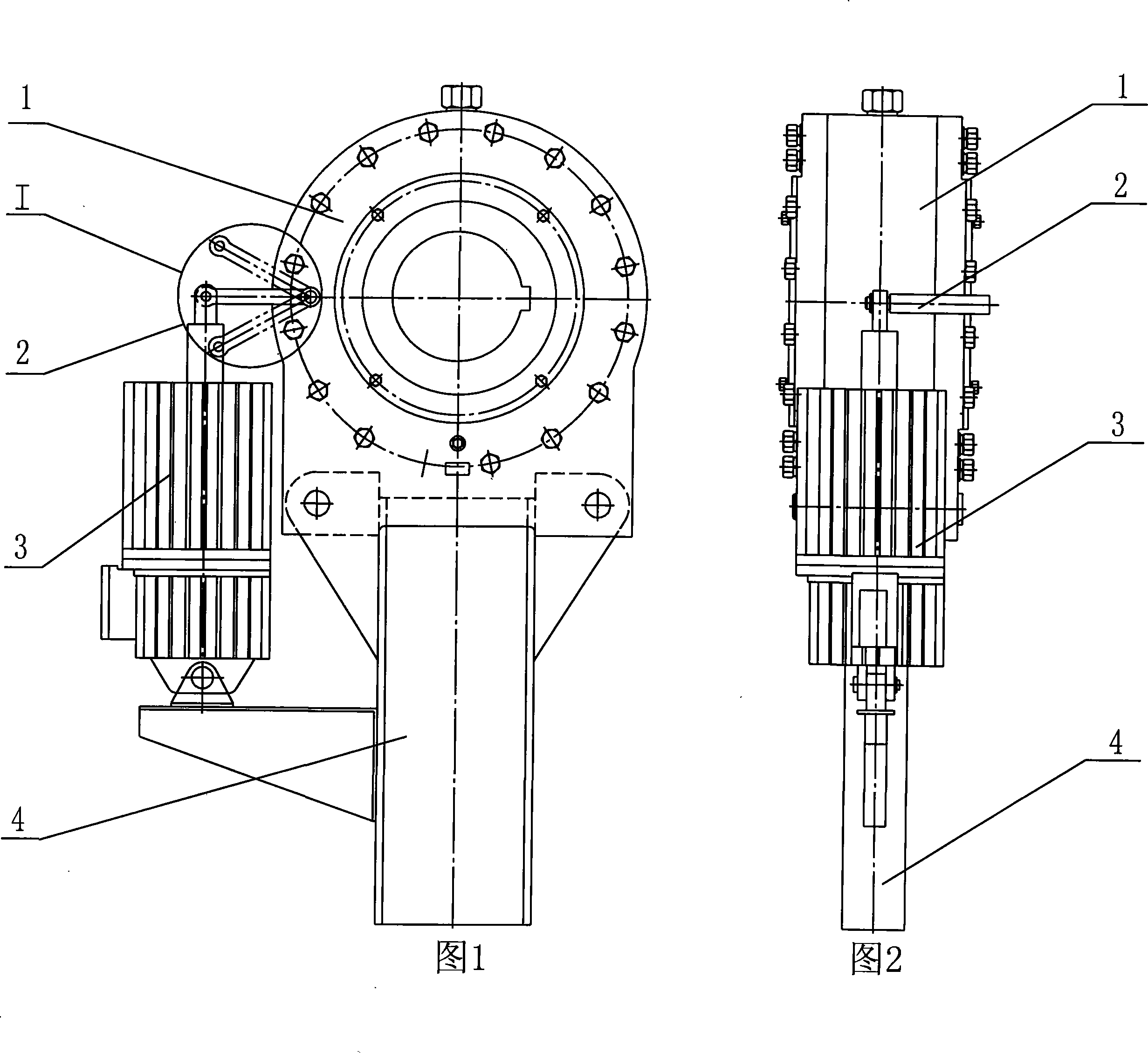
[0033] Referring to Figure 1 and Figure 2, a fork-type controllable non-contact wedge backstop is mainly composed of a backstop component 1, a shift fork component 2, a controller 3, an anti-rotation arm 4, and a wedge assembly 5 and other components; the backstop component 1 is installed on the top surface of the anti-rotation arm 4, and the controller 3 is installed on the anti-rotation arm 4, and is connected in series with the main machine of the conveying equipment such as a belt conveyor or a bucket elevator. Fork part 2 is connected with backstop part 1 and controller 3, and controller 3 is prior art, can adopt any one of electromagnetic mechanism, electrohydraulic pusher, pneumatic or hydraulic pusher etc.

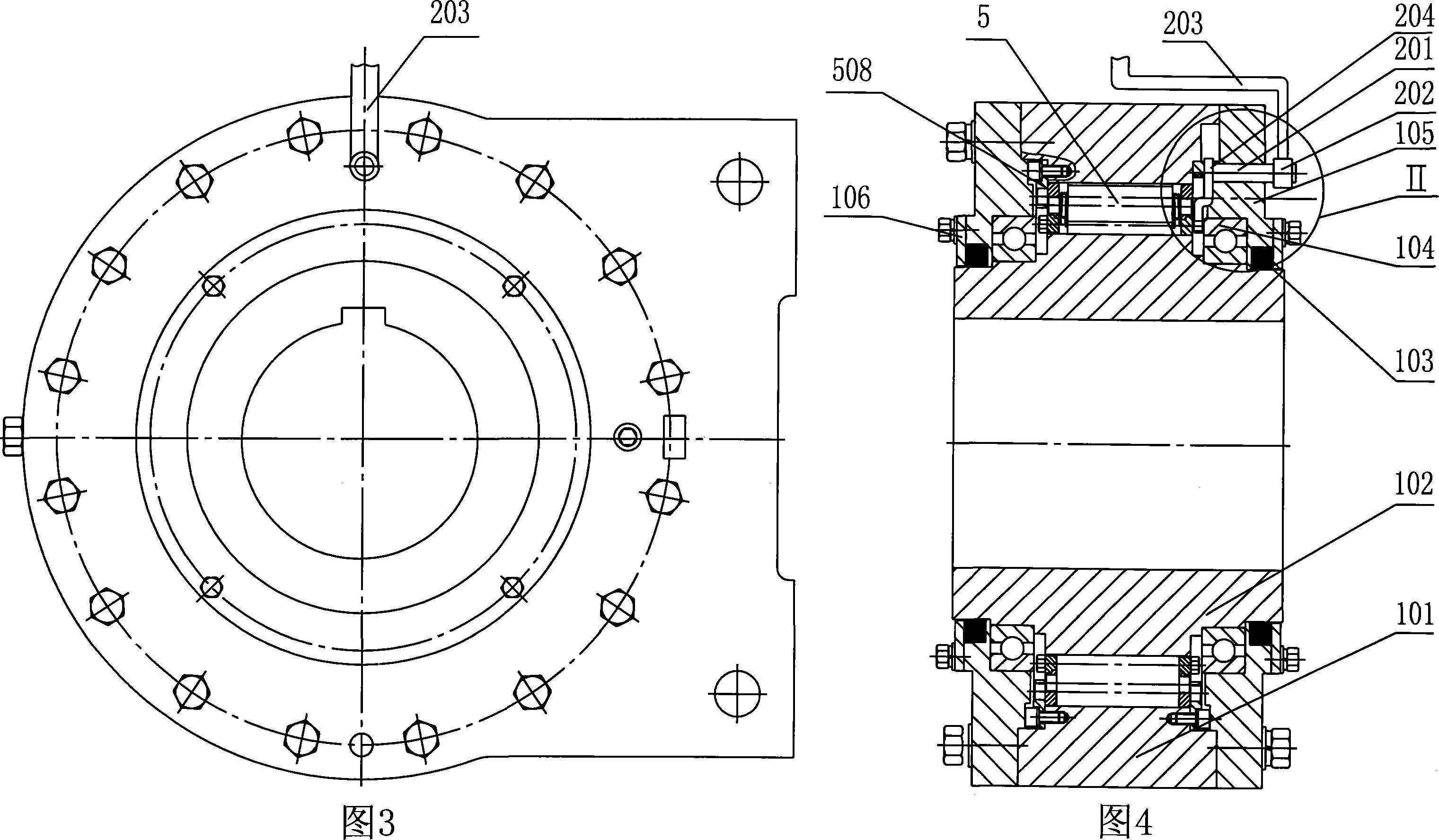
[0034] Referring to Fig. 3 and Fig. 4 at the same time, the backstop component 1 includes components such as an outer ring 101, an inner ring 102, a sealing ring 103, a bearing 104, an end cover 105, and a cover plate 106; A rolling bearing 104 and a sealing ring 1...

Embodiment 2

[0038] Referring to FIG. 9 and FIG. 10 , the shift fork part 2 can also protrude from the long hole on the end face of the end cover 105 of the backstop part 1 to connect with the controller 3 .

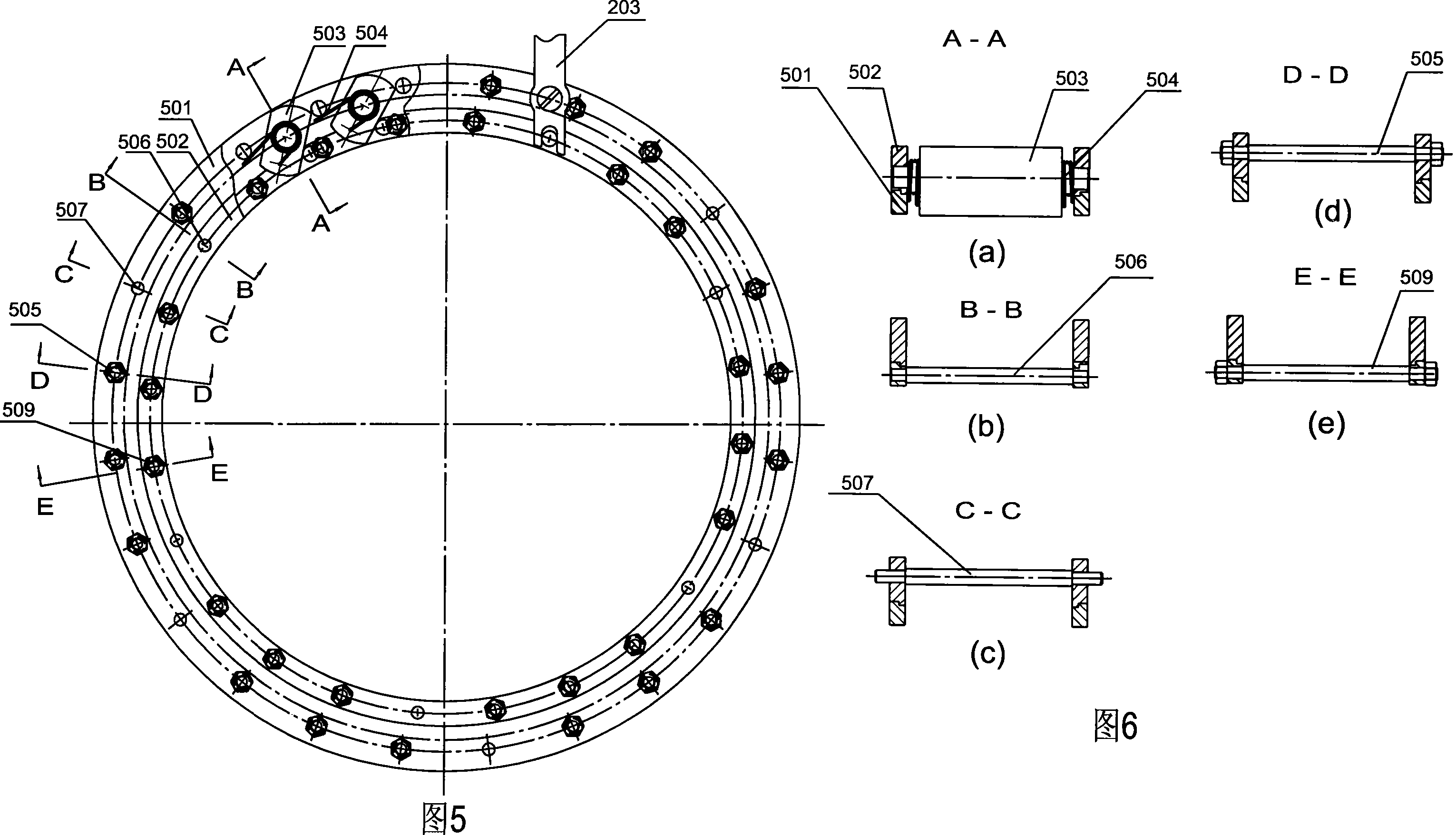
[0039] Referring to Fig. 11, Fig. 12 and Fig. 13, the inner end fork of the shift fork 204 of the shift fork part 2 is clamped on any shift ring positioning pin 506 of the shift ring 501, and the outer end is connected from the backstop part 1 The end cover 105 can protrude from the long hole provided on the end surface of the front end cover or the rear end cover, adopt packing or hair sticky seal, and connect the connecting rod 203 by bolts, and the connecting rod 203 is connected with the controller 3 . All the other structures of embodiment 2 are the same as embodiment 1.

Embodiment 3

[0041] Referring to FIG. 14 and FIG. 15 , the shift fork part 2 can also protrude from the circumference of the end cover 105 of the backstop part 1 to connect with the controller 3 .

[0042] Referring to Fig. 16, Fig. 17 and Fig. 18, the shift fork shaft 201 is arranged in the end cover 105, and the outer end of the shift fork shaft 201 is provided with a connecting rod 203, and the connecting rod 203 is connected from the end cap of the backstop component 1 105, which can protrude from the round hole on the circumference of the front end cover or the rear end cover to connect with the controller 3, the inner end of the shift fork shaft 201 is movably connected to the outer end of the shift fork 204, and the inner end of the shift fork 204 is locked Be installed on any dial ring positioning pin 506 of the dial ring 501. All the other structures of embodiment 3 are the same as embodiment 1.

[0043] Working principle of the present invention:

[0044] When the main unit of ...


PUM


Abstract

The invention relates to a fork type controllable non-contact wedge backstop. The backstop part and the controller are installed on the anti-rotation arm; the connecting rod of the shift fork part is connected with the controller, the inner ring of the backstop part is equipped with a bearing and a sealing ring, and the outer ring is equipped with front and rear end covers. The cover plate is installed on the end cover; the track formed between the outer ring and the inner ring is provided with a wedge assembly, and several wedges are arranged between the two yoke plates of the wedge assembly, and the two ends of the wedge are installed There is a torsion spring, and the two yoke plates and the two shifting rings are movably connected as a whole through the corresponding ring openings; the two fixed retaining rings of the wedge block assembly are provided with holes corresponding to the stop pins and the positioning pins of the yoke plates, and are connected to each other. Insert and assemble together; the inner end of the shift fork shaft of the shift fork part is movably connected with the outer end of the shift fork, the inner end of the shift fork is clamped on any shift ring positioning pin of the shift ring, and the shift fork The support point is movably connected with the corresponding yoke plate through screws, and the outer end of the shift fork shaft of the shift fork part protrudes from the round hole on the end face of the end cover of the backstop part to extend the connecting rod.

Description

technical field [0001] The invention belongs to the field of anti-reverse devices, and relates to a fork-type controllable non-contact wedge backstop. Background technique [0002] At present, contact or non-contact wedge backstops are generally used on belt conveyors, bucket elevators and other conveying equipment at home and abroad to prevent the equipment from being reversed due to the self-weight of the conveyed materials when the equipment is shut down, and to ensure that the equipment and personnel safety, especially the non-contact wedge backstop has been widely used; however, there are still some deficiencies in use: 1) Due to the uneven distribution of positioning pins and stop pins on the yoke plate and dial ring, The assembly process requirements of each component are strict, it is not convenient for serial processing, and the manufacturing cost is high; 2) Since the shift fork part protrudes from the circumference of the end cover to connect with the controller, ...

Claims


Application Information

Patent Timeline
Patent Type & Authority Applications(China)
IPC IPC(8): F16D71/00B65G43/00
Inventor 吕泽英
Owner 吕泽英
Learn More