Engagement type controlled non-contact wedge backstop

A backstop, non-contact technology, applied in the direction of brake type, conveyor control device, conveyor objects, etc., can solve the increase of backstop cost and daily maintenance, high contact stress on contact surfaces, and difficult backstop oil leakage And oil seepage and other problems, to achieve the effect of reducing daily maintenance, low cost and prolonging service life

Inactive Publication Date: 2010-12-29
吕泽英
View PDF6 Cites 0 Cited by
  • Summary
  • Abstract
  • Description
  • Claims
  • Application Information

AI Technical Summary

Problems solved by technology

[0002] At present, contact or non-contact wedge backstops are generally used on belt conveyors, bucket elevators and other conveying equipment at home and abroad to prevent the equipment from being reversed due to the weight of the material when the equipment is shut down, and to ensure that the equipment and The safety of personnel, especially the contact wedge backstop has been widely used on large-capacity, high-torque, high-inclination belt conveyors; however, there are still certain deficiencies in use: 1) due to the contact wedge When the block backstop is in normal operation of the main engine, the wedge and the inner and outer rings of the backstop are always in contact. Due to the friction force, the working temperature of the backstop is high, so it must be lubricated with high-grade steam engine oil, and it is extremely difficult to solve the backstop. 2) Since the wedge-type contact backstop relies on friction to overcome the backstop torque, the pressure between the wedge and the inner and outer rings is very high. Large, the contact stress on the contact surface is very high, the stress condition of the wedge is affected, and the working reliability is reduced; 3) Due to the uneven load distribution of the wedge, the wedge is destroyed successively, resulting in backstop failure, Reduce the life of the backstop; 4) Due to the uneven distribution of the positioning pins and stop pins on the yoke plate and dial ring, the assembly process requirements of each component are strict, it is not convenient for serial processing, and the manufacturing cost is high

Method used


Image

  • Engagement type controlled non-contact wedge backstop
  • Engagement type controlled non-contact wedge backstop
  • Engagement type controlled non-contact wedge backstop

Examples


Embodiment 1

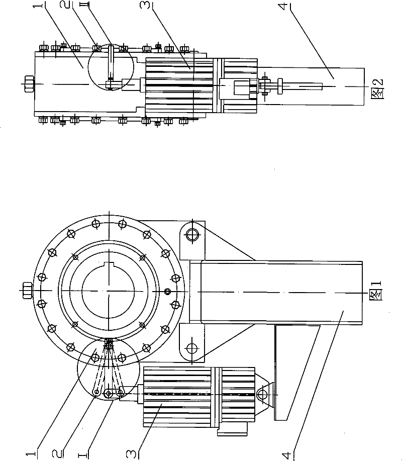
[0039] Referring to Fig. 1 and Fig. 2, an engaging controllable non-contact wedge backstop mainly consists of a backstop component 1, an engaging element 2, a controller 3, an anti-rotation arm 4, a wedge assembly 5, etc. Parts and components; the backstop component 1 is installed on the top surface of the anti-rotation arm 4, the controller 3 is installed on the anti-rotation arm 4, and is connected in series with the main machine of the conveying equipment such as belt conveyor or bucket elevator, and the engaging element 2 Connect with backstop component 1 and controller 3, controller 3 is prior art, can adopt any one of electromagnetic mechanism, electric hydraulic pusher, pneumatic or hydraulic pusher etc.

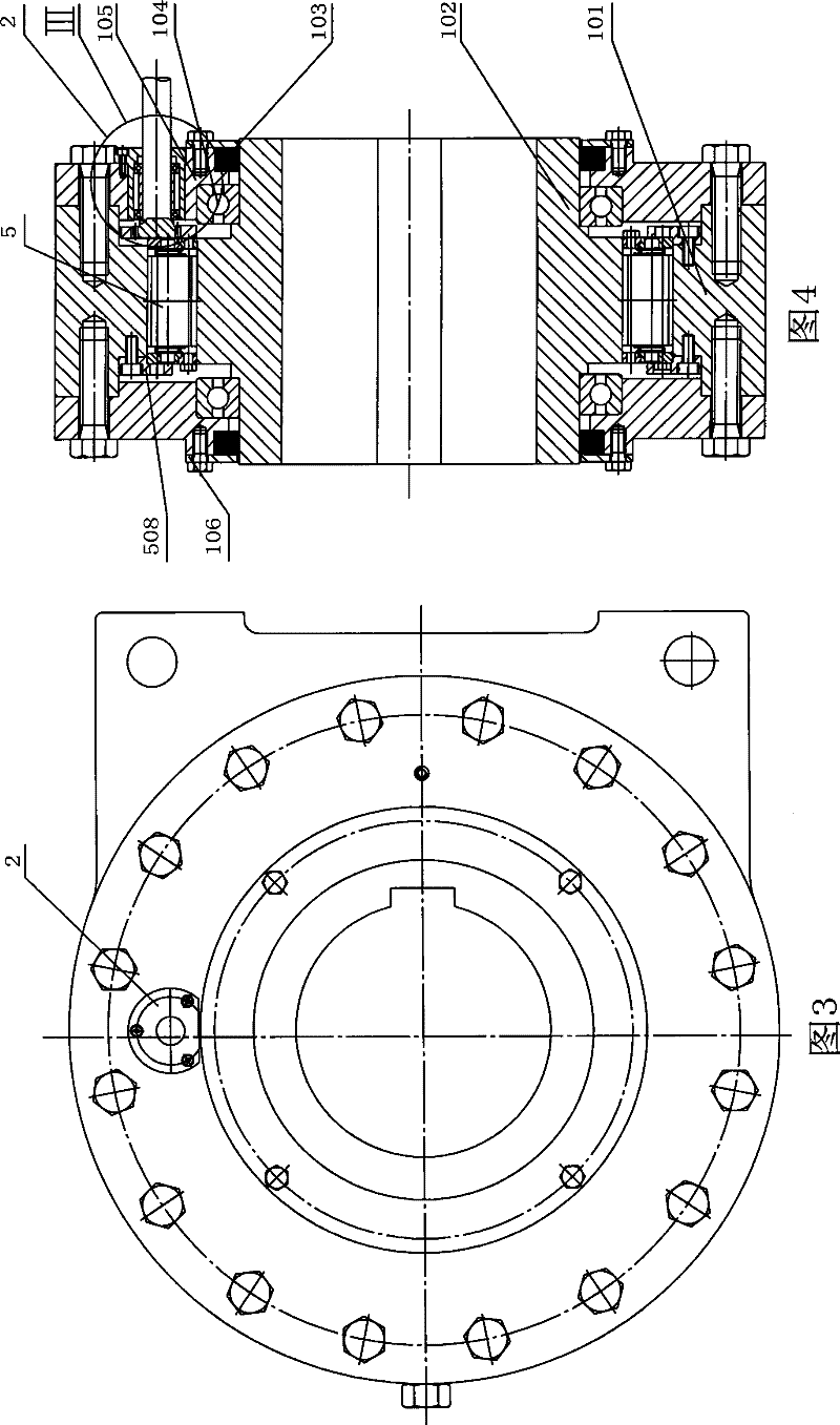
[0040] Referring to Fig. 3 and Fig. 4 at the same time, the backstop component 1 includes components such as an outer ring 101, an inner ring 102, a sealing ring 103, a bearing 104, an end cover 105, and a cover plate 106; A rolling bearing 104 and a sealing ring 103 ...

Embodiment 2

[0044] Referring to Fig. 10, Fig. 11, Fig. 12, and Fig. 13, the engaging element 2 can also protrude from the circumference of the end cover 105 of the backstop component 1 to connect with the controller 3 through an additional wheel shaft.

[0045] Referring to Fig. 14, Fig. 15, shown in Fig. 16 at the same time, described meshing element 2 also comprises components such as intermediate gear 207, intermediate gear shaft or rack 208, key 209; The intermediate gear 207 is connected by a key 209, the intermediate gear 207 meshes with the intermediate gear shaft or the rack 208, and one end of the intermediate gear shaft or the rack 208 is connected from the end cover 105, which can be a circular hole or a circular hole on the circumference of the front end cover or the rear end cover. Protrude from the long hole and use sealing ring or wool sticky, packing seal, connect with controller 3 through connecting rod 203; All the other structures of embodiment 2 are the same as embodim...

Embodiment 3

[0047] Referring to Fig. 17, Fig. 18, Fig. 19, and Fig. 20, the engaging element 2 can also protrude from the circumference of the end cover 105 of the backstop component 1 to connect with the controller 3 through an additional camshaft.

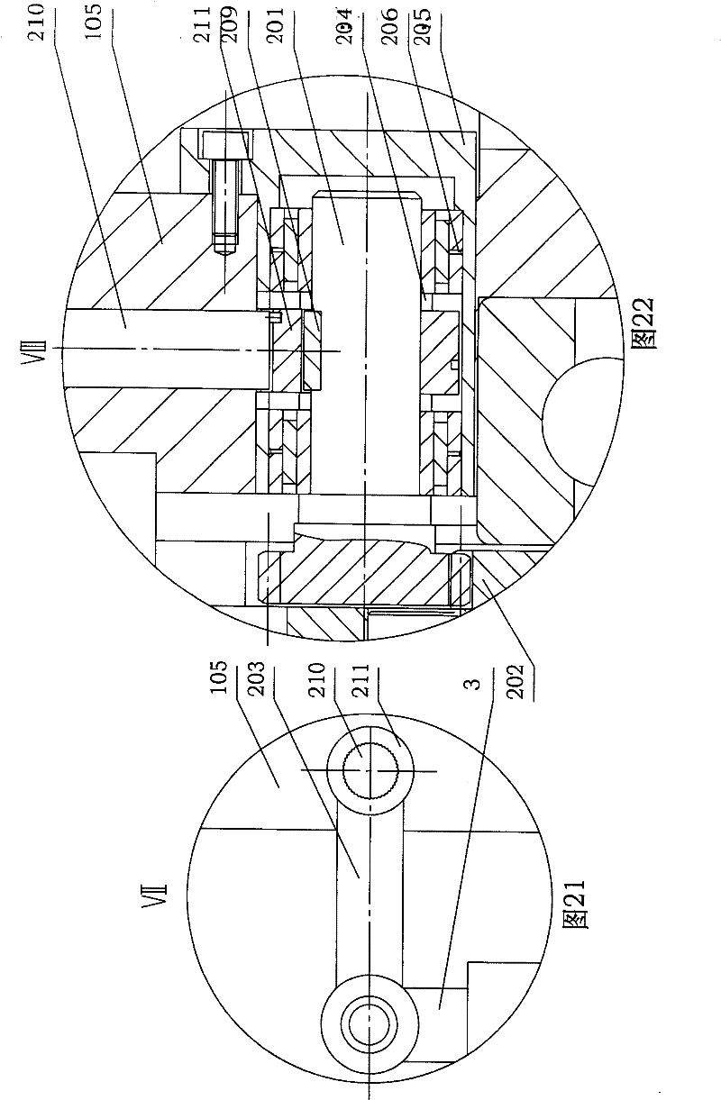
[0048] Referring to Fig. 21, shown in Fig. 22, described meshing element 2 also comprises parts and components such as camshaft 210, cam 211; Between two spacers 204 on its gear shaft 201, be connected with cam 211 by key 209, and cam 211 and The camshaft 210 cooperates, and one end of the camshaft 210 protrudes from the round hole on the circumference of the end cover 105, which can be the front end cover or the rear end cover, and is connected with the controller 3, and is sealed by a sealing ring; on one end of the gear shaft 201 The provided gear meshes with the rack 202 . All the other structures of embodiment 3 are the same as embodiment 2.


PUM


Abstract

The invention relates to a engagement-type controllable non-contact wedge block inverted device, which comprises a non-return member, a controller, a rotation-preventing arm and a wedge block assembly, wherein, the non-return member and the controller are arranged on the rotation-preventing arm; the inner ring of the non-return member is provided with a bearing and a seal ring, and the outer ringis provided with a front end cap and a rear end cap; cover plates are arranged on the end caps; the wedge block assembly is arranged in a rail formed between the inner ring and the outer ring; a plurality of wedge blocks are arranged between two yoke plates of the wedge block assembly; two ends of the wedge block are provided with torsion springs; the two yoke plates and two shift rings are integrated movably via ring openings which correspond mutually; two fixed stopping rings of the wedge block assembly are provided with holes corresponding to a stopping pin and a yoke plate positioning pinand are assembled together by mutual embedment; engaging elements are arranged in the end caps of the non-return member. The engagement force between gears and a gear chain is adopted to overcome inverted moments, the additional radial force produced during the force transmission can be significantly reduced, thereby improving the stress conditions of the wedge blocks, distributing loads evenly, facilitating the inverted device to run stably and reliably, and prolonging the service life of the inverted device.

Description

technical field [0001] The invention belongs to the field of anti-reverse devices, and relates to an engaging controllable non-contact wedge backstop. Background technique [0002] At present, contact or non-contact wedge backstops are generally used on belt conveyors, bucket elevators and other conveying equipment at home and abroad to prevent the equipment from being reversed due to the weight of the material when the equipment is shut down, and to ensure that the equipment and The safety of personnel, especially the contact wedge backstop has been widely used on large-capacity, high-torque, high-inclination belt conveyors; however, there are still certain deficiencies in use: 1) due to the contact wedge When the block backstop is in normal operation of the main engine, the wedge and the inner and outer rings of the backstop are always in contact. Due to the friction force, the working temperature of the backstop is high, so it must be lubricated with high-grade steam engi...

Claims


Application Information

Patent Timeline
Patent Type & Authority Patents(China)
IPC IPC(8): F16D71/00B65G43/00
Inventor 吕泽英
Owner 吕泽英
Why Eureka
Try Eureka