Capacity adjustable vortex compressor refrigeration system with main return loop installed with ejector

A scroll compressor, refrigeration system technology, applied in irreversible cycle compressors, compressors, refrigerators, etc., can solve the problem of high refrigerant pressure and temperature, large resistance coefficient of the discharge port, limited refrigerant discharge, etc. problems, to achieve the effect of simplifying design and control, improving adaptability, and reducing irreversible losses

Inactive Publication Date: 2008-04-30
TSINGHUA UNIV
View PDF0 Cites 9 Cited by
  • Summary
  • Abstract
  • Description
  • Claims
  • Application Information

AI Technical Summary

Problems solved by technology

In addition, in the actual system, the size of the refrigerant discharge port is limited by the wall thickness of the scroll body (too large discharge port will cause refrigerant leakage between different compression chambers, reducing the efficiency of the compressor), and the discharge port has a large drag coefficient
Therefore, the refrigerant leakage of the passive refrigerant leakage system that relies on the pressure difference between the compression chamber and the low-pressure side to achieve refrigerant leakage is very limited, and the pressure and temperature of the refrigerant that is finally unloaded are relatively high

Method used


Image

  • Capacity adjustable vortex compressor refrigeration system with main return loop installed with ejector
  • Capacity adjustable vortex compressor refrigeration system with main return loop installed with ejector
  • Capacity adjustable vortex compressor refrigeration system with main return loop installed with ejector

Examples


Embodiment 1

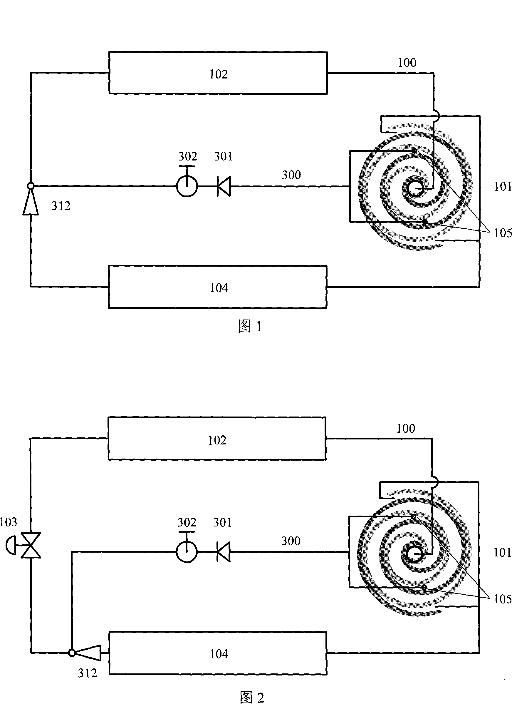
[0028] Fig. 1 is a structural schematic diagram of a scroll compressor refrigeration system using an ejector to enhance the refrigerant leakage function. The system includes a refrigerant primary circuit 100 and a refrigerant escape system. The main refrigerant circuit 100 is formed by sequentially connecting a scroll compressor 101 with a refrigerant discharge port 105 , a condenser 102 and an evaporator 104 . The refrigerant discharge system includes an ejector 312 and a refrigeration discharge circuit 300, wherein the ejector 312 is arranged on the pipeline between the condenser 102 and the evaporator 104 on the system refrigerant main circuit 100, and one end of the refrigerant discharge circuit 300 It is connected with the refrigerant injection hole 105 of the scroll compressor 101, and the other end is connected with the injection port of the injector 312 through the discharge one-way valve 301 and the discharge regulating valve 302 in sequence. The discharge one-way va...

Embodiment 2

[0032] Fig. 2 is another structural schematic diagram of a scroll compressor refrigeration system using an ejector to enhance the refrigerant leakage function. Comparing Fig. 1, it can be found that the system only adds a system expansion device 103 on the pipeline between the condenser 102 and the ejector 312 in the system main loop 100, thereby increasing the adjustability of the system. In actual operation, the expansion device 103 of the system is only used to control the superheat degree at the outlet of the evaporator 104, and the ejector 312 is only used to adjust the amount of refrigerant leakage, so that the adjustment effect of the system is guaranteed. In addition, when the injector 312 is a non-adjustable structure, the setting of the system expansion device 103 can also ensure the normal operation of the system. A system expansion device (103) is arranged on the pipeline of the inlet of the ejector (312) on the main refrigerant circuit (100) of the system.

Embodiment 3

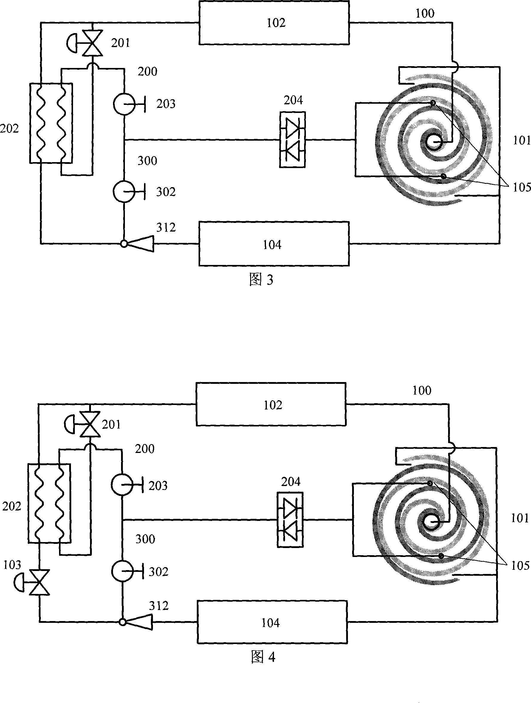
[0034] Fig. 3 is a structural schematic diagram of a scroll compressor refrigeration system using an ejector and an intermediate heat exchanger for refrigerant discharge and injection. The system includes three parts: a refrigerant main circuit 100, a refrigerant injection system and a refrigerant discharge system. The system refrigerant main circuit 100 is formed by sequentially connecting a scroll compressor 101 with a refrigerant injection port 105 , a condenser 102 and an evaporator 104 . The refrigerant discharge system includes an ejector 312 and a refrigeration discharge circuit 300, wherein the ejector 312 is arranged on the pipeline between the condenser 102 and the evaporator 104 on the system refrigerant main circuit 100, and one end of the refrigerant discharge circuit 300 It is connected to the refrigerant injection hole 105 of the scroll compressor 101, and the other end is connected to the injection port of the ejector 312 through the injection / discharge switchi...


PUM


Abstract

The invention relates to a whirl compressor cooling system which has a main loop provided with an ejector and the capacity adjustable, belonging to the cooling and air conditioning field. The ejector is arranged between the condenser and an evaporator in the system loop. The refrigerant is released from the middle section of the compressor to the low-pressure side by utilizing the high-low pressure differential reinforcing whirl compressor cooling system so as to improve the unloading capability of the whirl compressor. Meanwhile, the reinforced refrigerant release technique is combined with the refrigerant ejection technique so that the whirl compressor has the capacity change from the largest to the lowest greatly improved. The technique can be applied to the air conditioner cooling field with the cooling/heat pump system, thereby the efficiency, the system capacity and the performance of the compressor can be effectively changed, the highly efficient work of the system in larger work area can be achieved, and then the applicability of the system in large and changeable work condition is improved.

Description

technical field [0001] The invention relates to a refrigeration system with a scroll compressor, which belongs to the field of refrigeration and air conditioning. More specifically, it relates to a system form and control method for changing the capacity and performance of a refrigeration system containing a scroll compressor through refrigerant leakage or / and injection. Background technique [0002] A scroll compressor is a type of compressor used in refrigeration and air conditioning. Due to the advantages of high efficiency and low noise, scroll compressors are widely used in small and medium capacity refrigeration and air conditioning systems. The scroll compressor has a pair of symmetrically arranged scroll disks (stationary disk and moving disk), the static disk is fixed on the body of the compressor, and the moving disk performs circular translation around the static disk within a certain range. At the initial stage of compression, the low-pressure refrigerant gas i...

Claims


Application Information

Patent Timeline
Patent Type & Authority Applications(China)
IPC IPC(8): F25B1/04F25B9/08F25B41/00
CPCF25B1/04F25B2341/0011
Inventor 王宝龙石文星李先庭韩林俊
Owner TSINGHUA UNIV
Why Eureka
Try Eureka