A fuel circulation method for fuel battery and special device

A fuel cell, fuel cycle technology

Inactive Publication Date: 2008-04-30
SUNRISE POWER CO LTD
View PDF2 Cites 11 Cited by
  • Summary
  • Abstract
  • Description
  • Claims
  • Application Information

AI Technical Summary

Problems solved by technology

The outlet pressure of the pipeline fan is low, and it can only be used for fuel cells with a low pressure difference between the inlet

Method used


Image

  • A fuel circulation method for fuel battery and special device
  • A fuel circulation method for fuel battery and special device

Examples


Embodiment Construction

[0017] The present invention will be further described below in conjunction with the accompanying drawings and examples, but the scope indicated by the examples is not a limitation to the scope of protection claimed by the present invention.

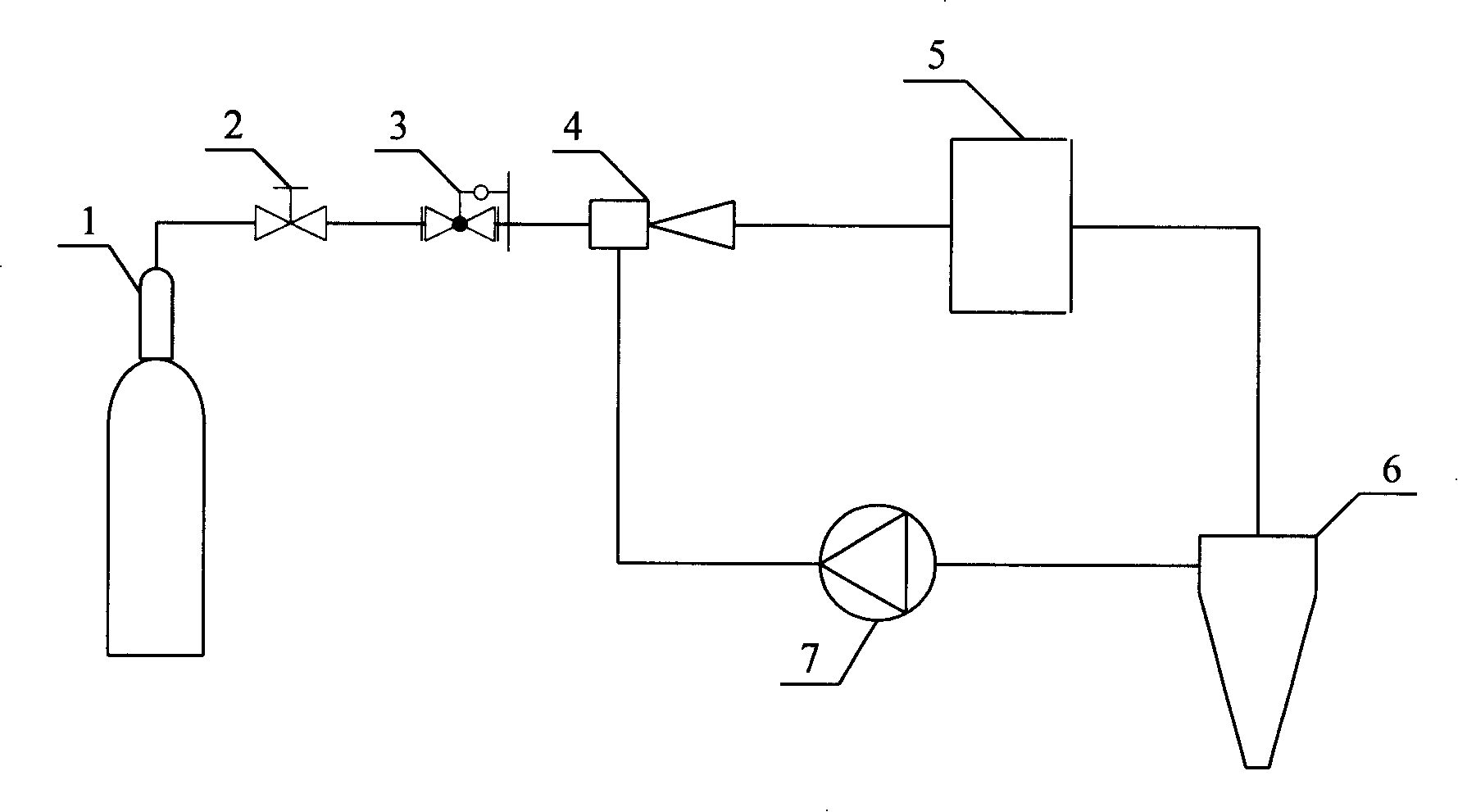
[0018] figure 1 It is a schematic diagram of the structure of the device for maintaining a constant cycle ratio of fuel cell anode fuel hydrogen in the full power range of the present invention.

[0019] Such as figure 1 As shown, the hydrogen storage tank 1 is connected to the inlet of the injector 4 through the control valve 2 (the inlet of the control valve 2 is connected to the outlet of the hydrogen storage tank 1, and the outlet is connected to the inlet of the pressure reducer 2), the pressure reducing valve 3 is connected to the inlet of the injector 4, and the injector 4. The outlet is connected with the inlet of the fuel cell stack 5, that is, the inlet of the injector 4 is connected with the outlet of the pressure reducer 3, ...


PUM


Abstract

The invention relates to an engine system for a fuel cell, which is a fuel circulation method for the fuel cell and a special device. The high-pressure fuel hydrogen gas from a hydrogen gas source passes a pressure reducing valve to reduce the pressure, enters into a hydrogen gas sprayer, the hydrogen gas from the sprayer goes into a fuel cell, after reaction with the fuel cell, the over-dose hydrogen gas and water generation from the reaction enter into a water separator together, the hydrogen gas from the water separator gas outlet goes into an air blower inlet, and the hydrogen gas pressurized by the air blower enters into the sprayer gas induction inlet. The sprayer design point is the pressure and flow rate of the consumed hydrogen gas at the fuel cell nominal power, the air blower can regulate the speed, through the regulating the air blower rotary speed, the fuel hydrogen gas can maintain approximately constant circulation ratio within the scope of the fuel cell full power. The invention meets the requirements of the fuel cell to hydrogen gas circulation with relatively little energy consumption, which can carry the water of the product out of the cell, can sufficiently utilize the fuel hydrogen gas, and the fuel can be more uniformly distributed at each single section of the cell, thereby further improving the fuel cell life.

Description

technical field [0001] The invention relates to a fuel cell engine system, in particular to a method and a device for maintaining a substantially constant circulation ratio of the anode fuel of the fuel cell within the full power range of the fuel cell. Background technique [0002] A fuel cell is a power generating device that converts chemical energy stored in fuel and oxidant directly into electrical energy. The inner core of a fuel cell device is the membrane electrode. At the anode end of the membrane electrode, the fuel can permeate through the porous material and undergo an electrochemical reaction on the surface of the catalyst, lose electrons and become positively charged ions, and the positive ions can migrate through the proton exchange membrane to reach The other end of the membrane electrode is the cathode end. At the cathode end of the membrane electrode, the gas containing the oxidant passes through the porous material and undergoes an electrochemical reacti...

Claims


Application Information

Patent Timeline
IPC IPC(8): H01M8/04H01M8/04089H01M8/04119
CPCY02E60/50
Inventor 王伟国王洪卫
Owner SUNRISE POWER CO LTD
Why Eureka
Try Eureka