Oscillation apparatus, jet stream generator and electronic equipment and vibration device manufacture method

A vibrating device and vibrating element technology, which can be applied to electric solid devices, electrical components, semiconductor devices, etc., can solve problems such as the inability of the gas to vibrate effectively and the deflection of the vibrating plate.

Inactive Publication Date: 2008-04-30
SONY CORP
View PDF4 Cites 30 Cited by
  • Summary
  • Abstract
  • Description
  • Claims
  • Application Information

AI Technical Summary

Problems solved by technology

On the other hand, although it is possible to increase the amount of gas blown by the device by increasing the vibration amplitude of the vibrating...

Method used


Image

  • Oscillation apparatus, jet stream generator and electronic equipment and vibration device manufacture method
  • Oscillation apparatus, jet stream generator and electronic equipment and vibration device manufacture method
  • Oscillation apparatus, jet stream generator and electronic equipment and vibration device manufacture method

Examples


Embodiment Construction

[0209] The following is a description of embodiments of the present invention with reference to the accompanying drawings.

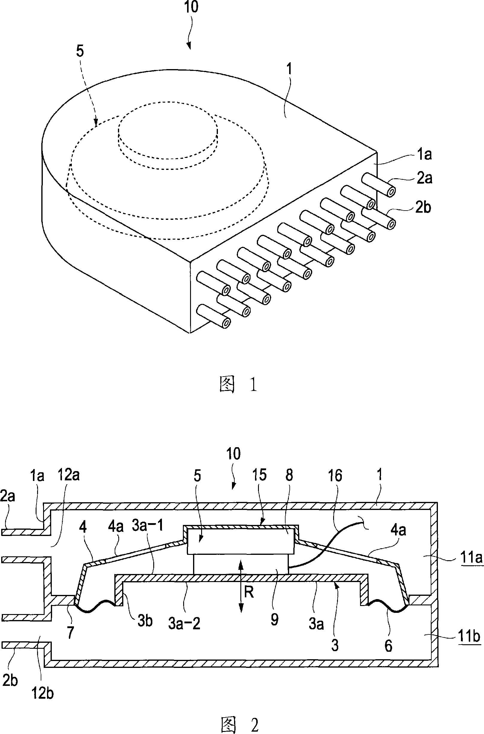
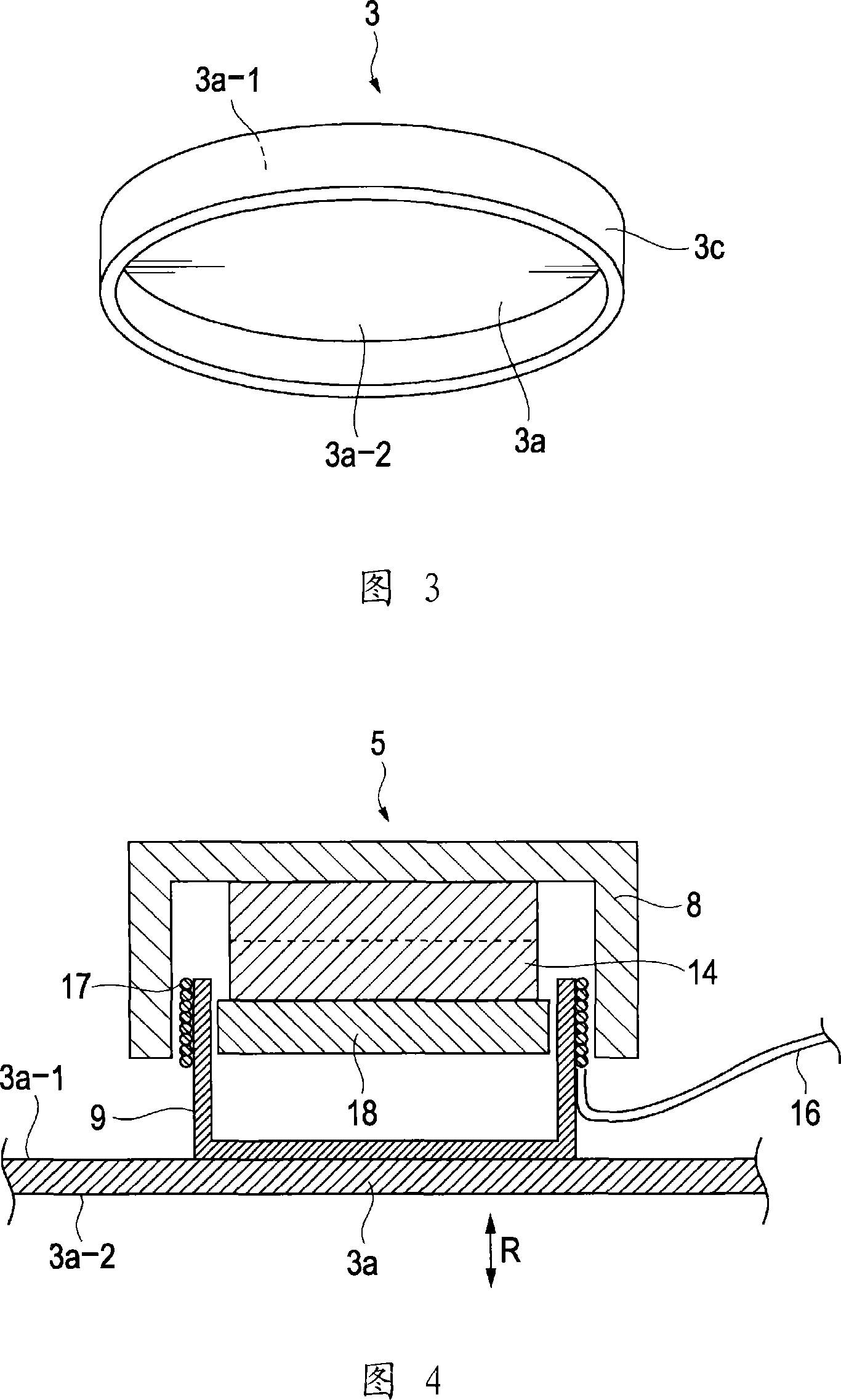
[0210] FIG. 1 is a perspective view illustrating a jet flow generating device according to an embodiment of the present invention, and FIG. 2 is a cross-sectional view of the jet flow generating device shown in FIG. 1 .

[0211] The jet flow generating device 10 has a housing 1 whose rear portion has a cylindrical shape, and a vibrating device provided in the housing 1 . A plurality of nozzles 2a and 2b are arranged on the front face 1a of the housing 1. As shown in FIG. As shown in FIG. 2 , the inside of the casing 1 is divided into an upper chamber 11 a and a lower chamber 11 b by a vibrating device 15 attached by means of an attachment portion 7 . On the front face 1a of the housing 1 where the nozzles 2a and 2b are provided, openings 12a and 12b are formed at positions corresponding to the nozzles 2a and 2b. Thus, the upper chamber 11a and the lowe...


PUM

PropertyMeasurementUnit
Remanent flux densityaaaaaaaaaa
Thicknessaaaaaaaaaa

Abstract

A vibrating device capable of effectively imparting vibration to a gas by efficiently generating vibration in a vibrator, a jet flow generating device having the vibrating device, an electronic device having the jet flow generating device, and a method of manufacturing the vibrating device. The jet flow generating device (10) comprises the vibrating device (15) having a frame (4), an actuator (5) mounted on the frame (4), and the vibrator (3) supported on the frame (4) through an elastic support member (6). The vibrator (3) is formed, for example, by forming a side plate (3b) at the peripheral edge part of a circular vibrating plate (3a). The vibrator (3) imparts vibration to the gas inside chambers (11a) and (11b) by vibrating to alternately discharge the gas through nozzles (2a) and (2b).

Description

technical field [0001] The present invention relates to a vibrating device for inducing vibrations in a gas jet, a jet generating device implementing the vibrating device, an electronic device implementing the jet generating device, and a method of manufacturing the vibrating device. Background technique [0002] There is known a problem related to an increase in heat generated from heat sources such as ICs (Integrated Circuits) in PCs (Personal Computers) due to an increase in the performance of PCs. One known method for dissipating heat involves contacting the IC with a heat sink formed, for example, of a metal such as aluminum or the like to dissipate heat from the IC by conduction through the heat sink. There is also a known method in which a fan is used to force out the hot air inside the PC case and introduce ambient air to the cooler, thereby dissipating the heat. There is also a known method in which a cooling fin and a fan are used simultaneously, whereby the conta...

Claims


Application Information

Patent Timeline
IPC IPC(8): H05K7/20G06F1/20H01L23/467
CPCH01L2924/0002
Inventor 石川博一中山典一牧野拓也武笠智治良尊弘幸
Owner SONY CORP
Why Eureka
Try Eureka