
Liquid crystal device and electronic equipment

一种液晶装置、液晶的技术,应用在非线性光学、仪器、光学等方向,能够解决折射率相位差不一致、对比度降低、不足明亮显示等问题,达到显示质量高、可靠性提高的效果

Inactive Publication Date: 2008-05-07
JAPAN DISPLAY INC
View PDF1 Cites 12 Cited by
  • Summary
  • Abstract
  • Description
  • Claims
  • Application Information

AI Technical Summary

Problems solved by technology

However, in the case of white display in the reflective region, the phase difference in the transmissive region is λ / 4, which is not sufficient for bright display
Therefore, the refractive index phase difference (retardation) between the transmissive display area and the reflective display area does not match, and thus there is a problem that the contrast of the display is lowered.

Method used


Image

  • Liquid crystal device and electronic equipment
  • Liquid crystal device and electronic equipment
  • Liquid crystal device and electronic equipment

Examples


no. 2 approach

[0088] Next, a second embodiment of the liquid crystal device according to the present invention will be described with reference to FIGS. 5 and 6. FIG.

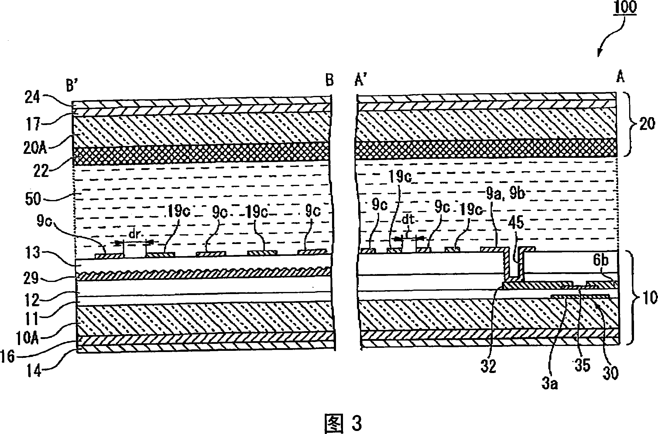
[0089] 5 is a plan view showing an arbitrary sub-pixel region of the liquid crystal device 200 of this embodiment, and FIG. 6 is a partial cross-sectional view taken along lines A-A' and B-B' in FIG. 5 .

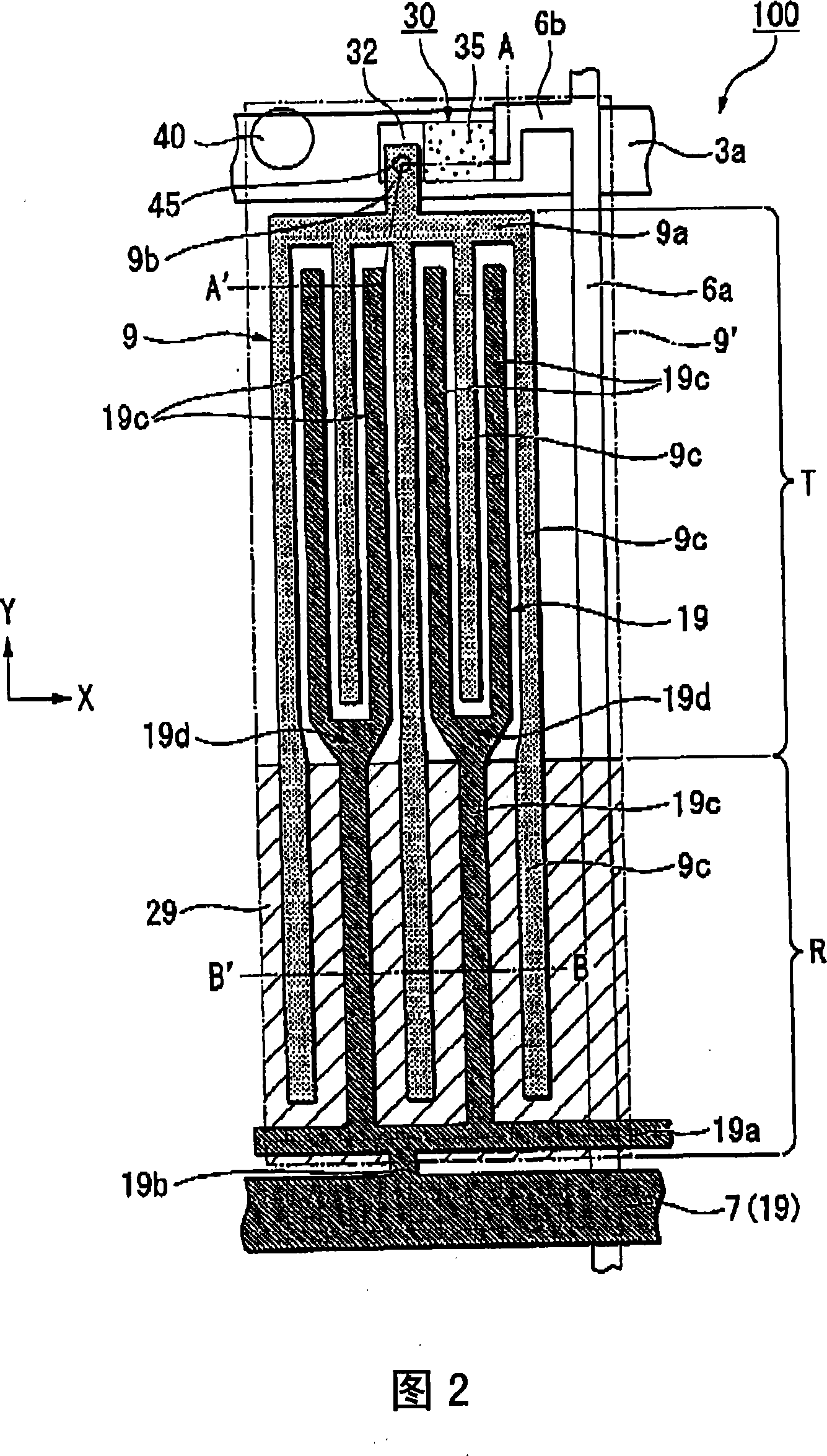
[0090]Furthermore, the basic structure of the liquid crystal device 200 of this embodiment is the same as that of the previous first embodiment, and the difference from the above-mentioned first embodiment is that the shapes of the pixel electrodes and the common electrodes are different. FIG. 5 is a diagram corresponding to FIG. 2 of the first embodiment, and FIG. 6 is a diagram corresponding to FIG. 3 of the first embodiment. Therefore, in each of the drawings referred to in this embodiment, components common to the liquid crystal device 100 of the first embodiment shown in FIGS. instruction of.

[0091] According to t...


PUM


Abstract

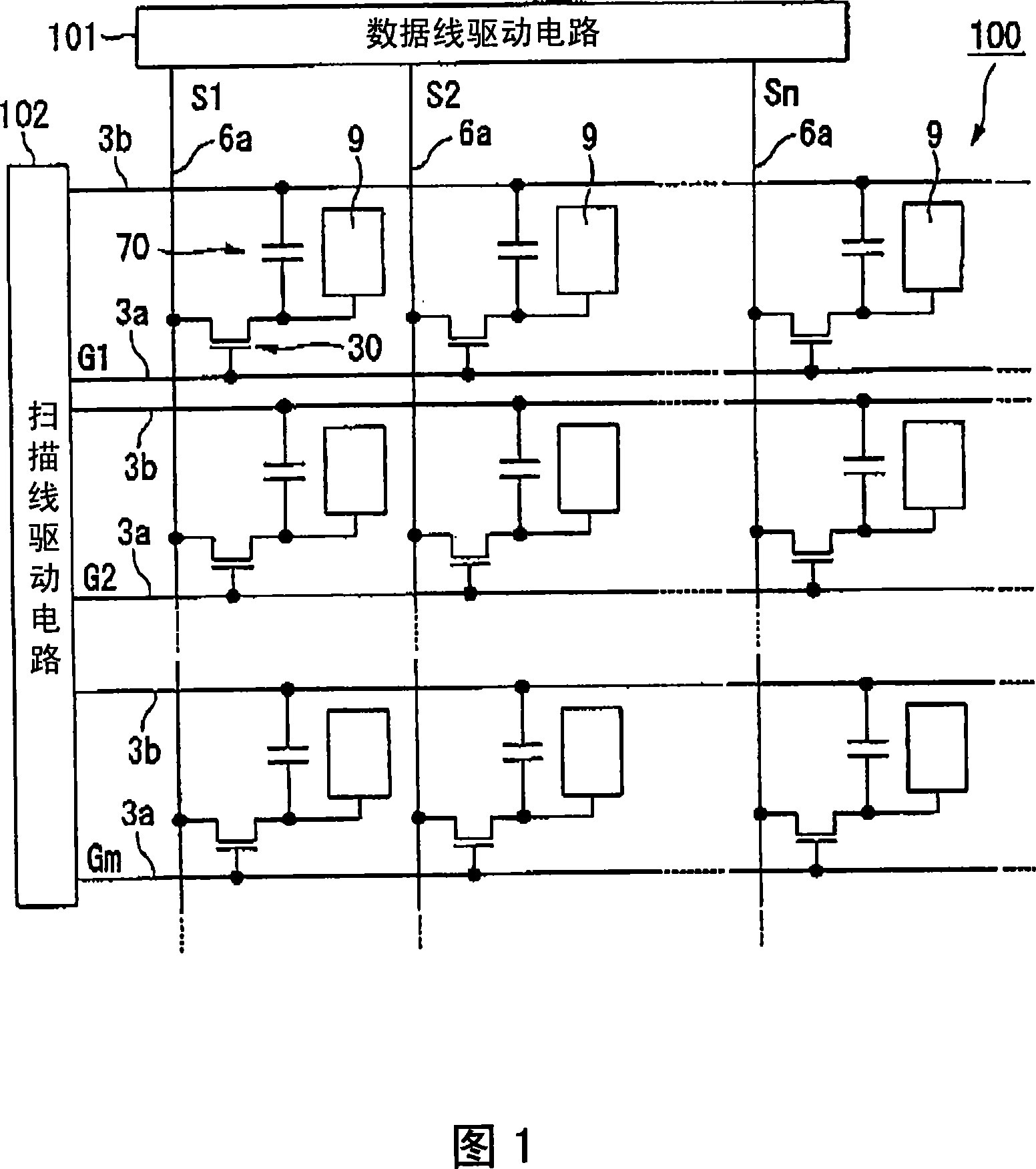
The present invention provides a liquid crystal device and electric device. The liquid crystal device includes a liquid crystal layer having liquid crystal which demonstrates an optically isotropic property when no electric field is applied and demonstrates an optically anisotropic property which is proportional to the square of the electric field strength when electric field is applied, and a pair of substrates which sandwich the liquid crystal layer, including sub-pixel areas (9') each including a reflective display area for reflective display and a transmissive display area for transmissive display; and first and second electrodes (9, 19) provided in both of the reflective display area and the transmissive display area, wherein the liquid crystal layer is driven by an electric field generated between the first electrode (9) and the second electrode (19), and wherein the distance between the first electrode (9) and the second electrode (19) in the transmissive display area is smaller than the distance between the first electrode (9) and the second electrode (19) in the reflective display area.

Description

technical field [0001] The present invention relates to a liquid crystal device and electronic equipment. Background technique [0002] In recent years, a display method using electron polarization using the electro-optical effect has been proposed. The electro-optical effect refers to a phenomenon in which the refractive index of a substance changes due to an external electric field. As the electro-optical effect, for example, it is known as the Kerr effect. The Kerr effect refers to a phenomenon in which, when an electric field is applied to an isotropic polar substance, birefringence is excited in proportion to the square of the electric field intensity with the direction of the electric field as the optical axis. As a liquid crystal material that develops such a Kerr effect, a blue phase is known. The blue phase is an optically isotropic liquid crystal phase that appears in a specific temperature range between the chiral nematic phase and the isotropic phase. Its res...

Claims


Application Information

Patent Timeline
Patent Type & Authority Applications(China)
IPC IPC(8): G02F1/1362G02F1/133G02F1/1343G09G3/36
CPCG02F2001/133541G02F1/13731G02F2001/134372G02F1/13718G02F1/133555G02F1/134363G02F1/133541G02F1/134372G02F1/1335
Inventor 春山明秀
Owner JAPAN DISPLAY INC
Learn More