
System and method for recognizing problems of micro-actuator piezoelectric elements

A micro-actuator and piezoelectric element technology, applied in the manufacture/assembly of piezoelectric/electrostrictive devices, piezoelectric devices/electrostrictive devices, instruments, etc., can solve problems such as inability to work

Inactive Publication Date: 2008-05-07
SAE MAGNETICS (HK) LTD
View PDF5 Cites 5 Cited by
  • Summary
  • Abstract
  • Description
  • Claims
  • Application Information

AI Technical Summary

Problems solved by technology

Unfortunately, they may not work at all when there is only a single piezoelectric element in the system
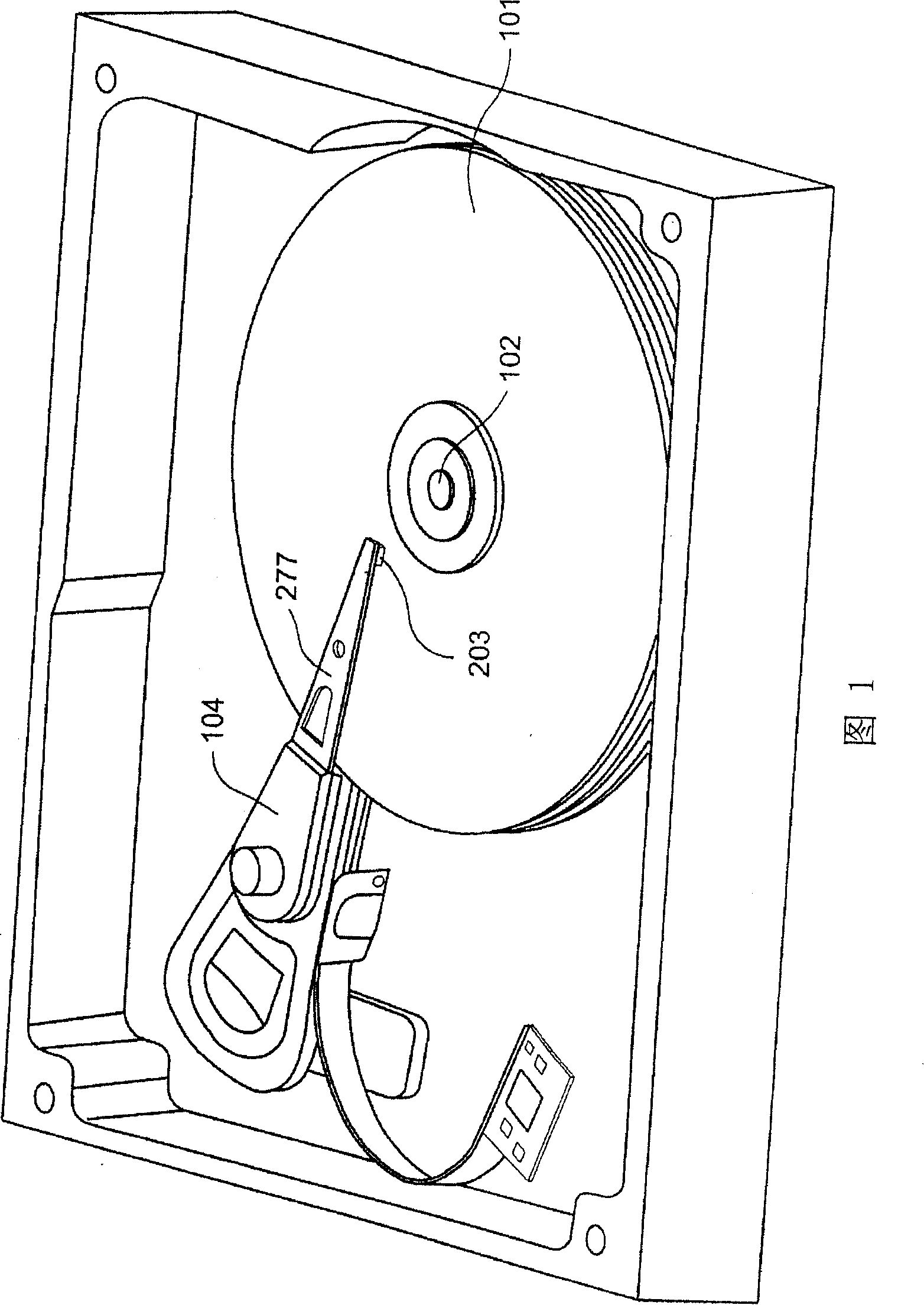
This can happen in hard drive sensor systems

Method used


Image

  • System and method for recognizing problems of micro-actuator piezoelectric elements
  • System and method for recognizing problems of micro-actuator piezoelectric elements
  • System and method for recognizing problems of micro-actuator piezoelectric elements

Examples


Embodiment Construction

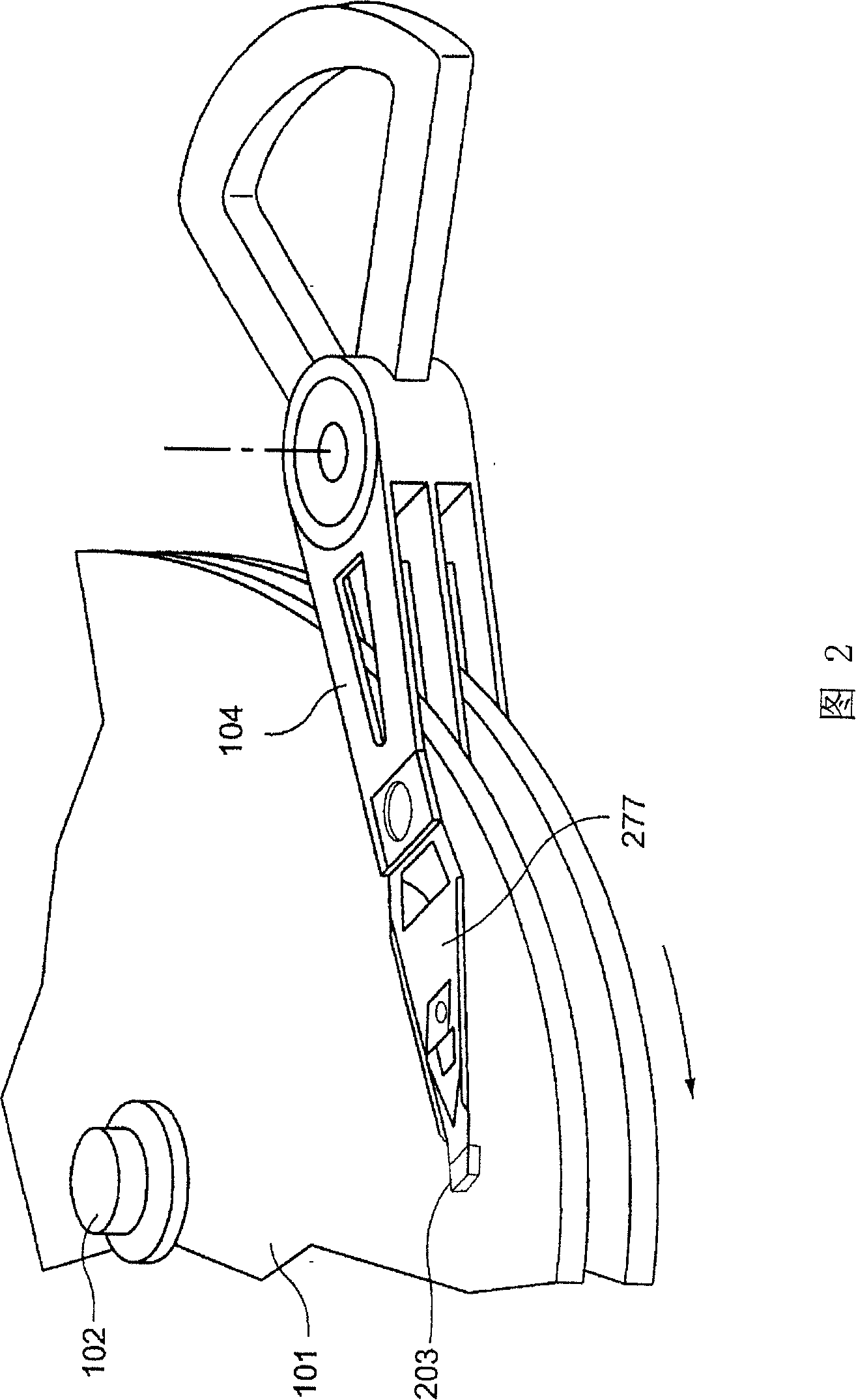
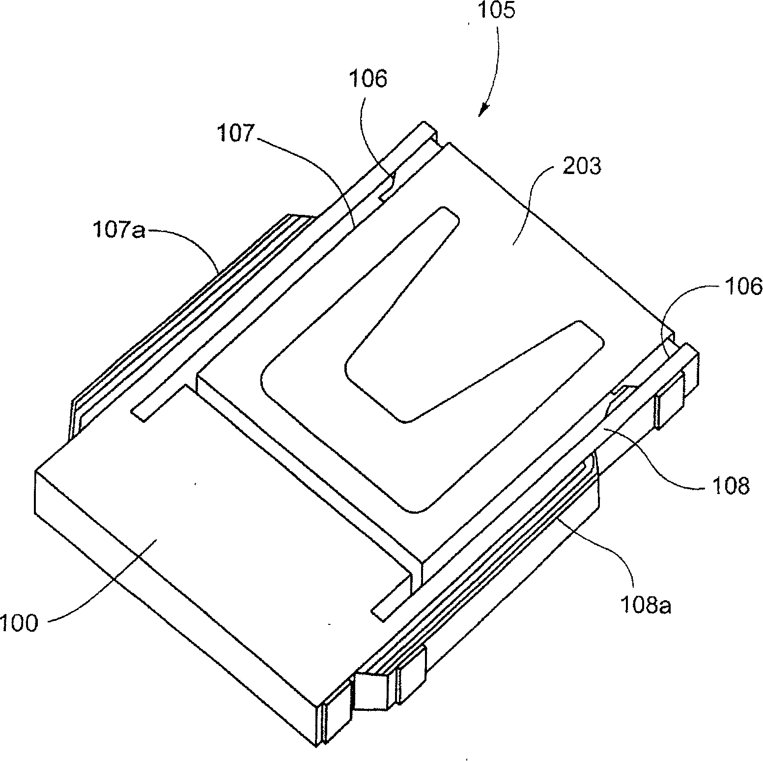
[0038] Several embodiments of the invention provide techniques for identifying problems (eg, microcracks, deformation, etc.) that exist within the piezoelectric element of a microactuator. The reference cell and the test cell can be induced to vibrate by applying a voltage (eg, a sinusoidal voltage) across the reference cell. Whether there is a problem with the test unit can be determined by comparing (eg, with a processor) corresponding resonance characteristics (eg, frequency, amplitude, phase, etc.). The reference unit may include a HGA or HSA of a hard disk drive. The testing device may comprise corresponding components for detection. This technique enables detection of piezoelectric element problems when each microactuator has only one piezoelectric element.

[0039] Figure 4a-4b An exemplary source device 401 of the test system according to several embodiments of the present invention is shown; Fig. 4c-4d shows an exemplary receiving device of the test system accordi...


PUM


Abstract

The invention provides a system and a method for identifying the problem of a microactuator piezoelectric element. In a plurality of embodiments, a voltage (for example, sinusoidal voltage) can be exerted to a reference unit to cause the vibration of the reference unit and a testing unit. Through the comparison (for example, under the assistance of a processor) to each resonance characteristic (for example, the frequency, the oscillation amplitude and the phase position), whether the testing unit has problems is determined. The reference unit can comprise a head gimbal assembly or a head stack assembly of a hard disk drive. The testing unit can comprise corresponding parts used for detecting. The technology can detect the problem of the piezoelectric element under the circumstance that each microactuator only has one piezoelectric element.

Description

technical field [0001] The present invention relates to an information recording disk drive unit, and more particularly to a technique for identifying problems associated with a piezoelectric element of a microactuator of a head gimbal assembly of a hard disk drive. Background technique [0002] A common information storage device is a magnetic disk drive unit, which uses magnetic media to store data and selectively reads data from the magnetic media or writes data to the magnetic on the medium. [0003] Consumers have always expected increasing storage capacity from such disk drive systems, while at the same time expecting faster and more accurate read and write speeds. Therefore, disk manufacturers have been devoting themselves to developing disk systems with higher storage capacity, such as increasing the density of magnetic tracks by reducing the track width or track spacing on the disk, thereby indirectly increasing the storage capacity of the disk. However, as the tr...

Claims


Application Information

Patent Timeline
IPC IPC(8): G11B5/00G11B5/012G11B5/596G11B21/10G01R29/22H01L41/09H01L41/22
Inventor 姚明高
Owner SAE MAGNETICS (HK) LTD
Learn More