

Method for detecting signal in multi-antenna digital communication system
A communication system and multi-antenna technology, which is applied in the field of signal detection, can solve the problems of increasing the complexity of detection signal algorithms, achieve the effects of reducing computational complexity, simplifying computational complexity, and improving computational stability
- Summary
- Abstract
- Description
- Claims
- Application Information
AI Technical Summary
Problems solved by technology
Method used
Image

Examples
Embodiment 1
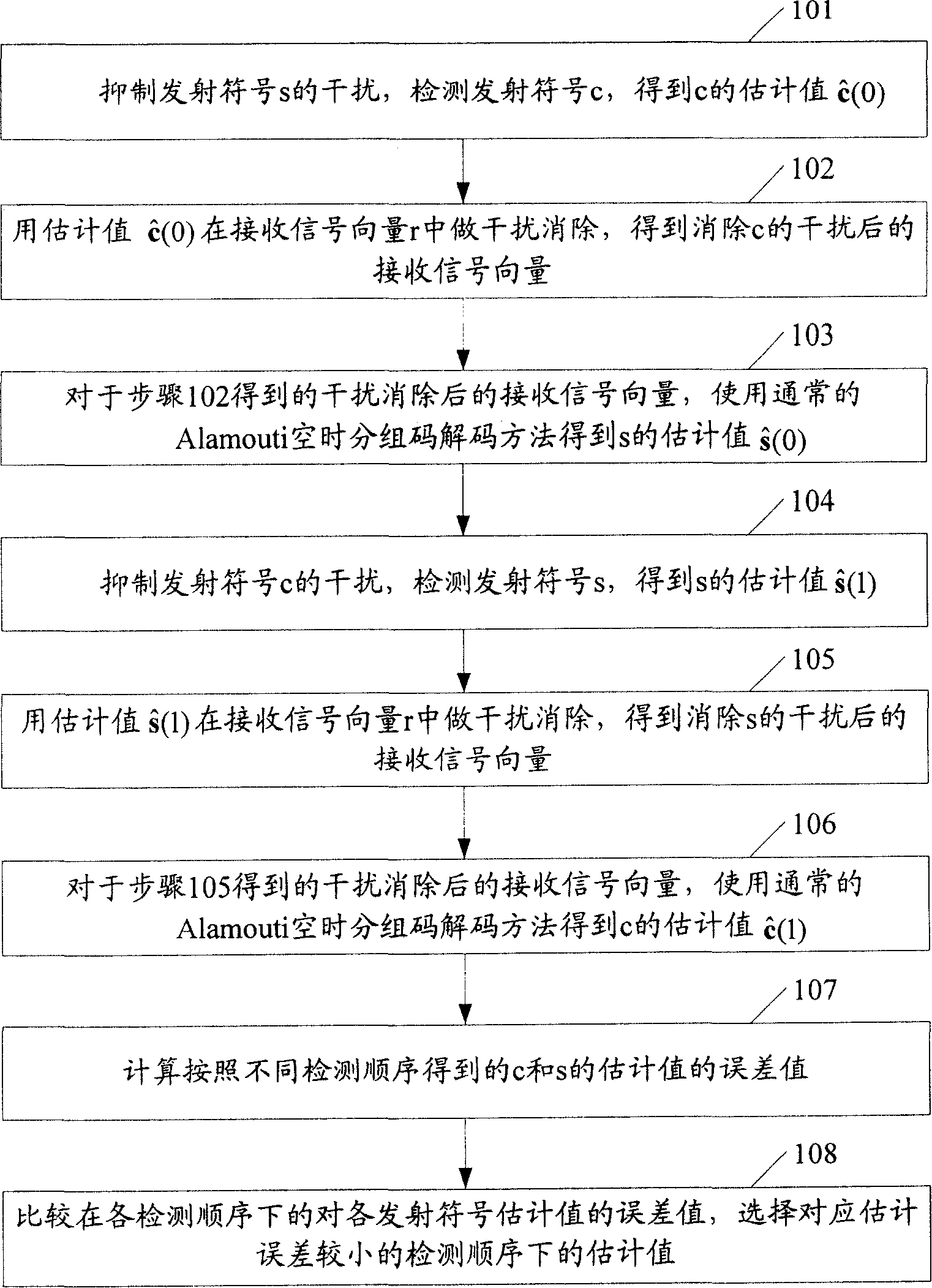
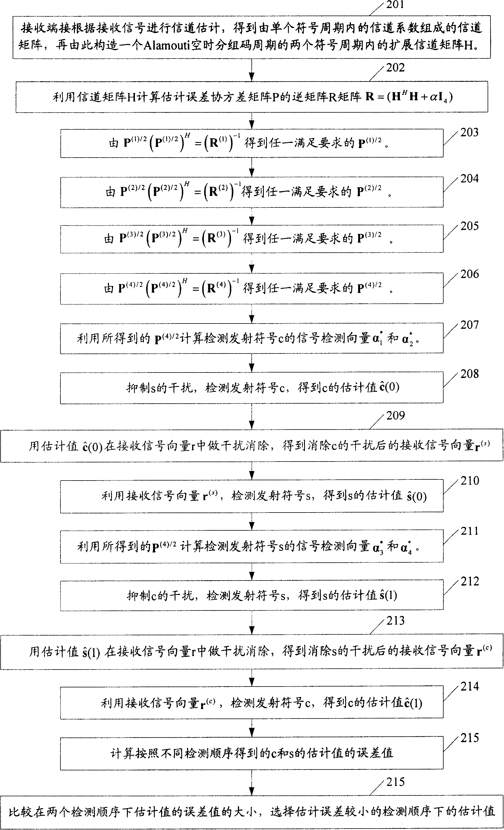
[0090] In Embodiment 1, the transmitting end transmits two groups of symbols, and each group of symbols is converted into a channel signal by channel coding with an Alamouti space-time block code encoder. Assume that the transmitter has 4 transmit antennas, and each 2 transmit antennas transmit a set of Alamouti space-time block codes respectively, where each set of Alamouti space-time block codes is a channel obtained by channel encoding two symbols through an Alamouti space-time block code encoder Signal; the receiving end has 2 transmitting antennas, and the 2 transmitting antennas at the receiving end receive all channel signals transmitted by the transmitting antenna of the transmitting end, and detect all symbols transmitted by the transmitting antenna of the transmitting end. figure 2 It is a flow chart of detecting signals in Embodiment 1, including the following steps:
[0091] Step 201: The receiving end receives two sets of channel signals respectively transmitted ...
Embodiment 2
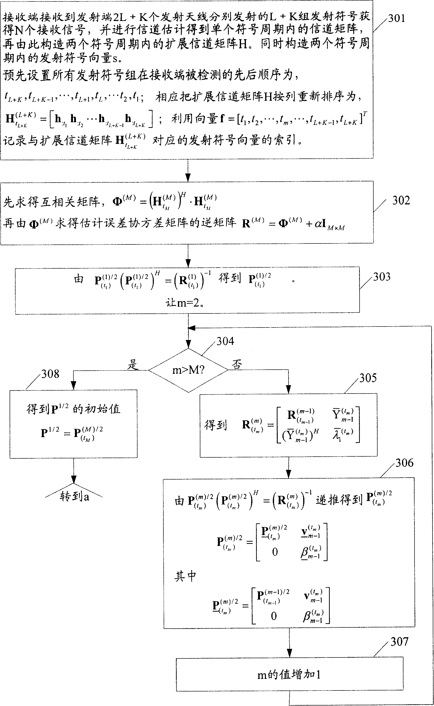
[0140] Embodiment 2 provides a method for detecting signals using received signals received by N receiving antennas at the receiving end when 2L+K transmitting antennas at the transmitting end transmit L groups of Alamouti space-time block codes plus K groups of symbols. Among them, 2L transmit antennas transmit L groups of Alamouti space-time block codes obtained by channel coding L groups of symbols through an Alamouti space-time block code encoder, and K transmit antennas directly transmit K groups of symbols. image 3 Before detecting the signal in this embodiment, recursively P 1 / 2 The flow chart of the initial value includes the following steps:
[0141] Step 301: After receiving the L groups of Alamouti space-time block codes and K groups of symbols respectively transmitted by the transmitter from 2L+K transmit antennas, the receiving end obtains N received signals, and performs channel estimation based on the received signals to obtain a single symbol A channel matrix...
Embodiment 3
[0232] In the second embodiment, when seeking P corresponding to all transmitted symbol groups 1 / 2 In the recursive process of the initial value, that is, in each recursion of step 303 and step 306, there is a step of finding the square root of a real number, and there is a serial relationship between this step and other steps, that is, it must be in this After the steps are completed, the following steps can be performed. In order to avoid the negative impact of the above steps of finding the square root of real numbers on other steps, P 1 / 2 The initial value can also be deduced by another method. Embodiment three is given below, and the use of LDL is given T Decomposition Factor Recursion P 1 / 2 method for the initial value.
[0233] Embodiment three:
[0234] Embodiment 3 also provides a method for detecting signals by using received signals received by N receiving antennas at the receiving end when 2L+K transmitting antennas at the transmitting end transmit the L group...
PUM
 Abstract
Description
Claims
Application Information