Guide bar shogging mechanism

The invention relates to a technology of bar traversing and moving device, which is applied in textile and papermaking, knitting, warp knitting and other directions, and can solve the problems of increased meshing gap between screw and nut, inaccurate bar traverse, and unfavorable maintenance. Achieve the effect of smooth motion, compact structure and low cost

Inactive Publication Date: 2011-01-19
王占洪
View PDF5 Cites 0 Cited by
  • Summary
  • Abstract
  • Description
  • Claims
  • Application Information

AI Technical Summary

Problems solved by technology

The nut cannot rotate with the screw rod because it is fixed on the ejector rod parallel to the screw rod, but it can move linearly along the screw rod. Therefore, when the servo motor controls the rotation of the screw rod, the nut can drive the ejector rod to control the movement of the bar. Traversing overcomes the above-mentioned shortcomings of the original warp knitting machine bar traverse device, such as the small traverse distance, but because the device is too simple, the screw nut is directly exposed, which is not conducive to maintenance; The nut affects the linear motion of the ejector rod, and at the same time, the unfavorable influence of the torque will be further increased due to the different axes of the ejector rod and the screw rod; the scattered dust accelerates the wear of the screw rod and the nut; The meshing gap between them increases, which leads to inaccurate horizontal movement of the comb bar, which makes the effective life shorter

Method used


Image

  • Guide bar shogging mechanism
  • Guide bar shogging mechanism
  • Guide bar shogging mechanism

Examples


Embodiment Construction

[0015] The accompanying drawings disclose two specific embodiments of the present invention without limitation, and the present invention will be further described below in conjunction with the accompanying drawings.

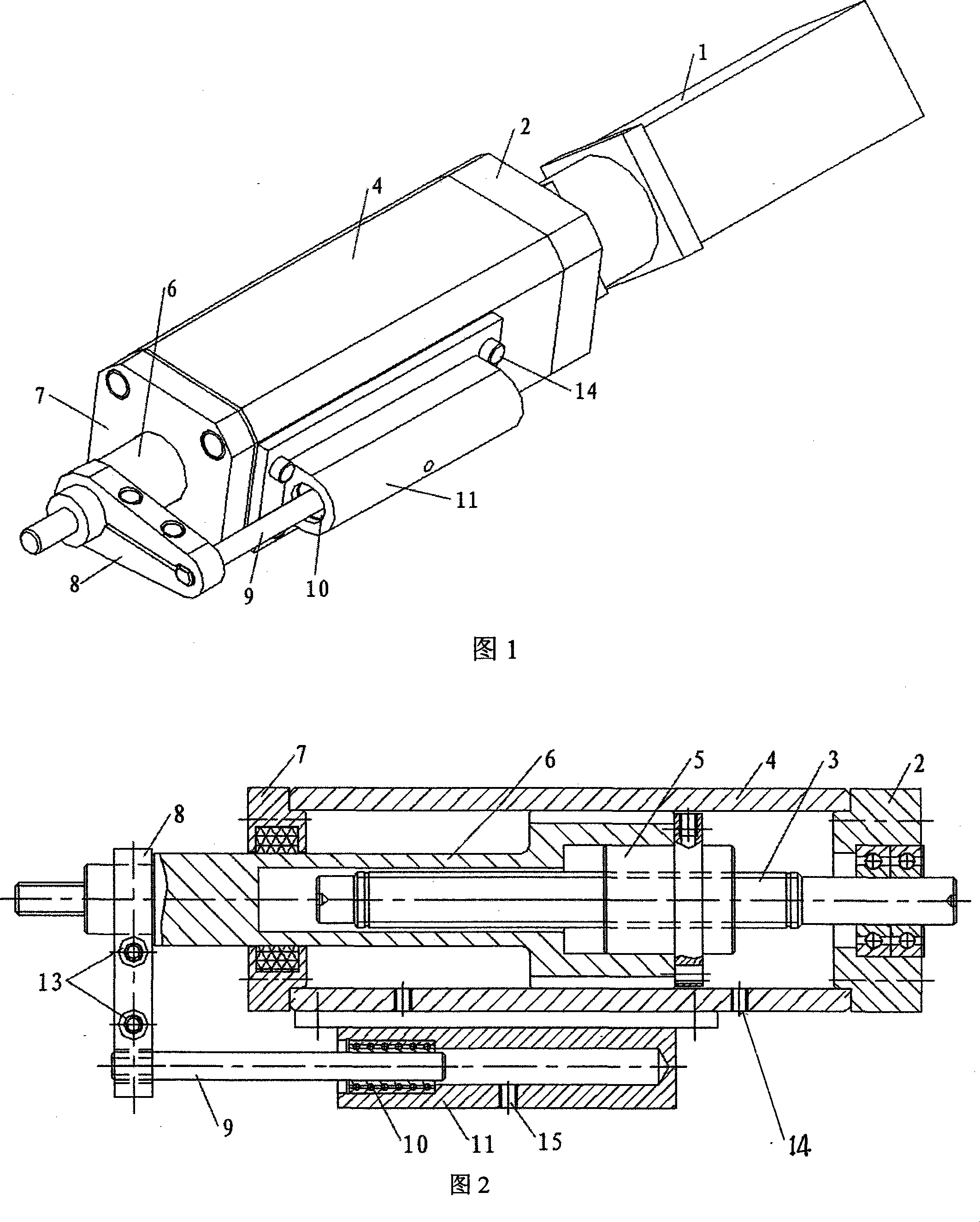
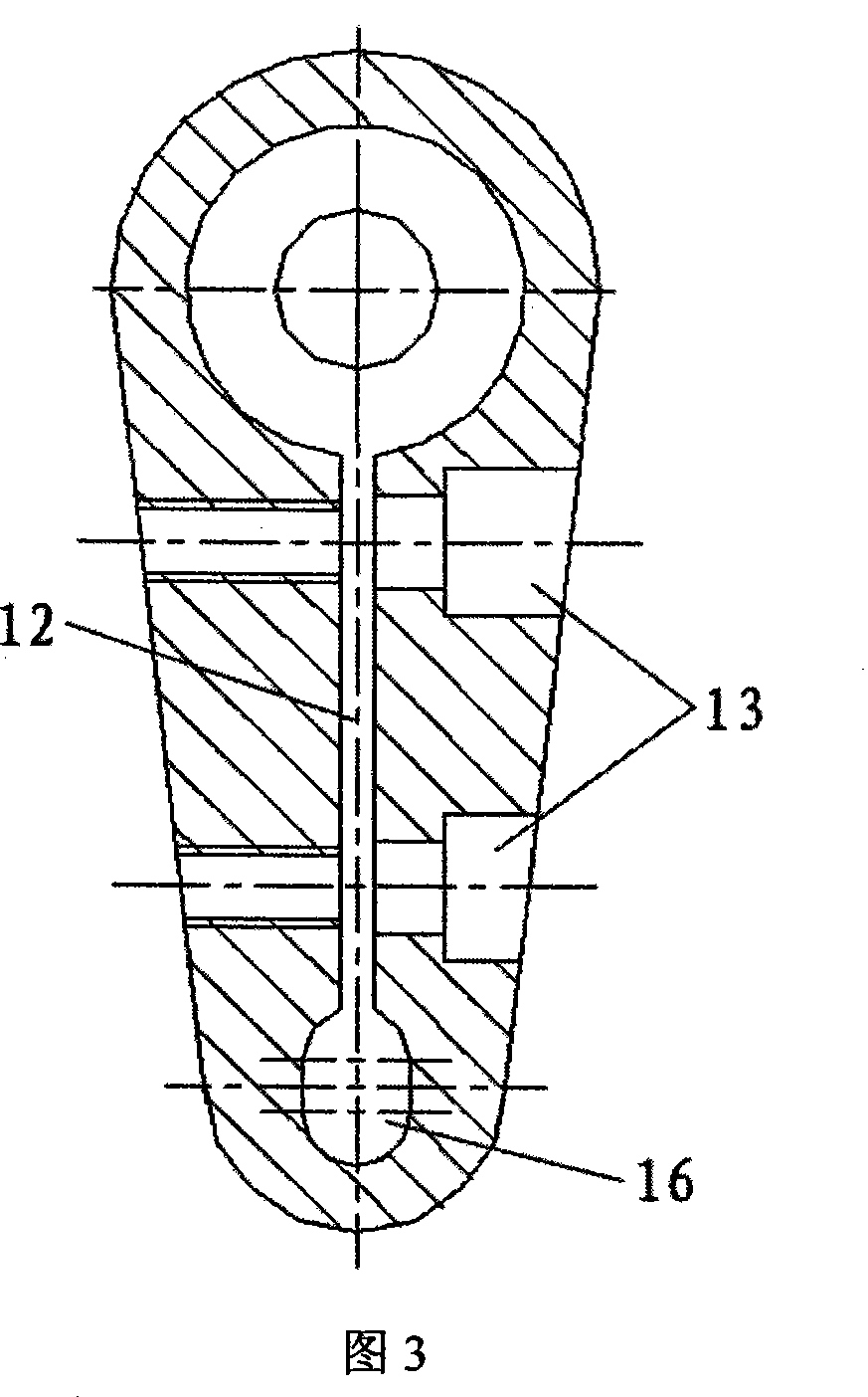
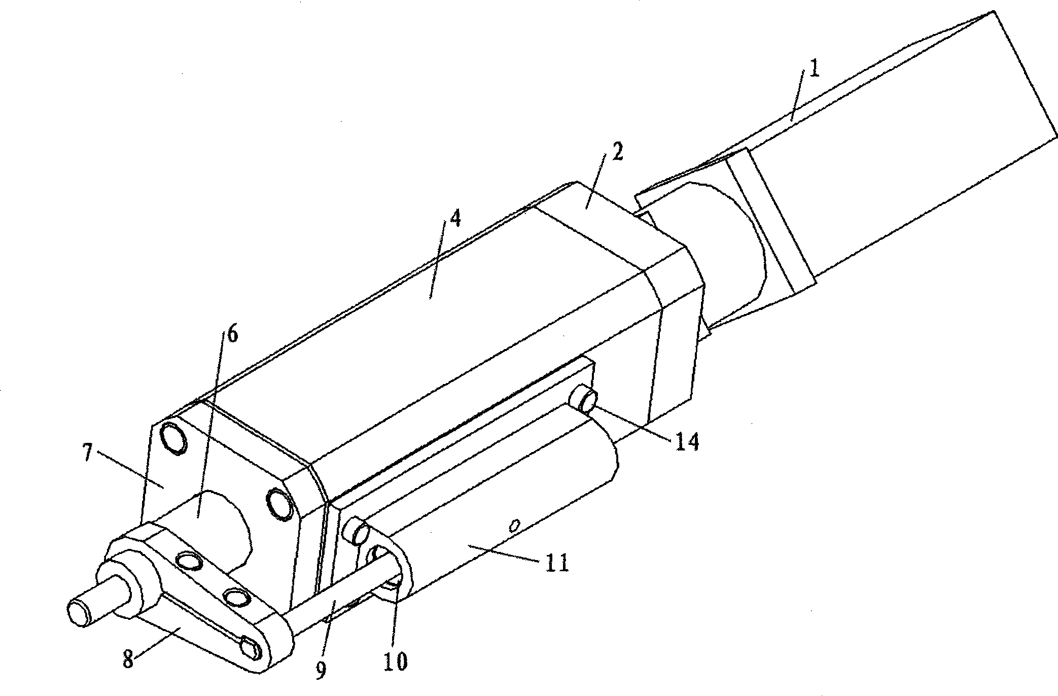
[0016] See the accompanying drawings, 1 in the figure is the servo motor, 2 is the bearing housing, 3 is the ball screw, 4 is the sleeve, 5 is the ball nut, 6 is the push rod shaft, 7 is the end cover, 8 is the connecting rod, 9 Is telescopic shaft, and 10 is linear bearing, and 11 is supporting body, and 12 is connected seam, and 13 is screw hole, and 14 is screw, and 15 is oil hole, and 16 is connecting rod hole.

[0017] The bar traversing device of the present invention includes a servo motor 1 and a mover, the mover is composed of a main mover and an auxiliary mover, the auxiliary mover is fixed in parallel on the outside of the main mover, and the servo motor 1 is installed On the bearing seat 2 of the device, the telescopic shaft 9 of the auxiliary mover ...


PUM


Abstract

The invention relates to a traverser of guide bar, consisting of a service motor and a locomotory apparatus. The locomotory apparatus consists of a main locomotory apparatus and an auxiliary locomotory apparatus; the auxiliary locomotory apparatus is fixed on the outer side of the main locomotory apparatus in a parallel way; the service motor is positioned on a bearing seat of the main locomotoryapparatus; a retractable shaft of the auxiliary locomotory apparatus is fixedly connected with a pushing rod shaft of the main locomotory apparatus through a connecting rod. As the pushing rod shaft and a ball screw are on the same axis and the auxiliary locomotory apparatus is arranged on one side of the pushing rod shaft and connected with the pushing rod shaft through the connecting rod, the torsion on the pushing rod shaft is removed by the retractable shaft and is no longer output, and the traversing error of the pushing rod shaft is reduced due to diminished gap between the ball screw and a ball nut, thereby improving the precision and lengthening the service life of the traverser; meanwhile, the ball nut and the ball screw are arranged in a sealed sleeve, which is not only good forensuring product quality but also good for maintaining and preventing dust from entering, further with the advantages of low cost, simple and compact structure, etc.

Description

technical field [0001] The invention relates to a warp knitting machine, in particular to a bar traverse device on the warp knitting machine, belonging to the field of textile machinery. Background technique [0002] The control device of the bar traversing device on the original warp knitting machine is composed of faceplates or chain blocks. Less, poor lateral movement accuracy (with cumulative error), cumbersome operation, large space occupation and high noise. And the control device of the bar traversing on the existing warp knitting machine is mainly made up of servo motor, screw mandrel, nut and ejector rod, nut is sleeved on the screw mandrel, one end of ejector rod is fixedly connected with nut one side, and the other end of ejector rod is connected with nut. Bar connection. The nut cannot rotate with the screw rod because it is fixed on the ejector rod parallel to the screw rod, but it can move linearly along the screw rod. Therefore, when the servo motor controls...

Claims


Application Information

Patent Timeline
Patent Type & Authority Patents(China)
IPC IPC(8): D04B27/26
Inventor 王占洪
Owner 王占洪
Why Eureka
Try Eureka