High-temperature solar heat pipe receivers

A technology of solar heat pipes and high temperature heat pipes, which is applied in the directions of solar collectors, solar thermal energy, solar thermal power generation, etc., can solve the problems of affecting the efficiency of heat absorption, limiting, reducing the thermal efficiency of receivers, etc., and achieves the advantages of convenient processing and low cost Effect

Inactive Publication Date: 2008-05-14
NANJING UNIV OF TECH
View PDF3 Cites 9 Cited by
  • Summary
  • Abstract
  • Description
  • Claims
  • Application Information

AI Technical Summary

Problems solved by technology

[0009] 1. Due to the use of ordinary cylindrical high-temperature heat pipes, the heat-absorbing section is cylindrical, and the normal direction of the surface receiving sunlight has a large angle with the incident light, which affects the heat-absorbing efficiency;
[0010] 2. Due to the large gap between each heat pipe in the heat-absorbing section, a large part of the sunlight does not directly irradiate the wall of the heat pipe, which further reduces the thermal efficiency of the receiver;
[0011] 3. The receiver involved in this patent mainly considers the heat storage function, which limits the adaptability of the receiver to different power generation systems, because if the number of heat pipes is small, the heat stored will not be enough to maintain the work of the receiver
Therefore, the design power of the receiver cannot be adjusted at will, but the number of heat pipes must be adjusted under the condition of satisfying the heat storage, which brings great limitations to the use of the receiver.

Method used


Image

  • High-temperature solar heat pipe receivers
  • High-temperature solar heat pipe receivers

Examples


Embodiment Construction

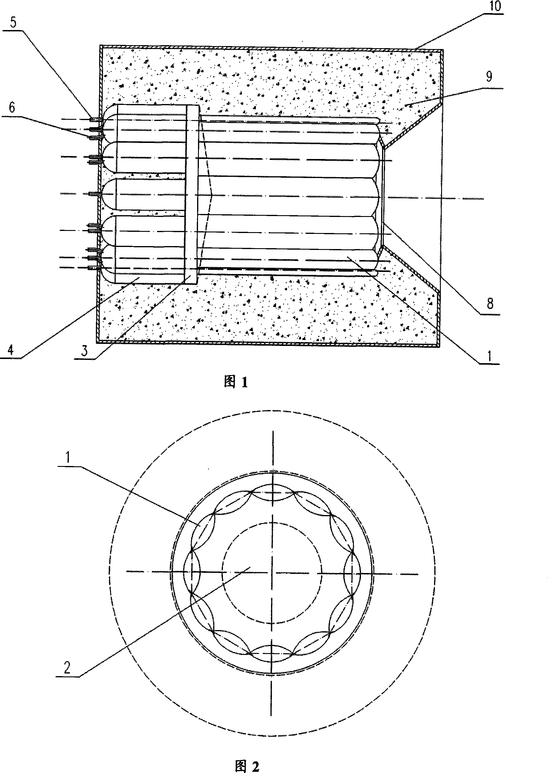
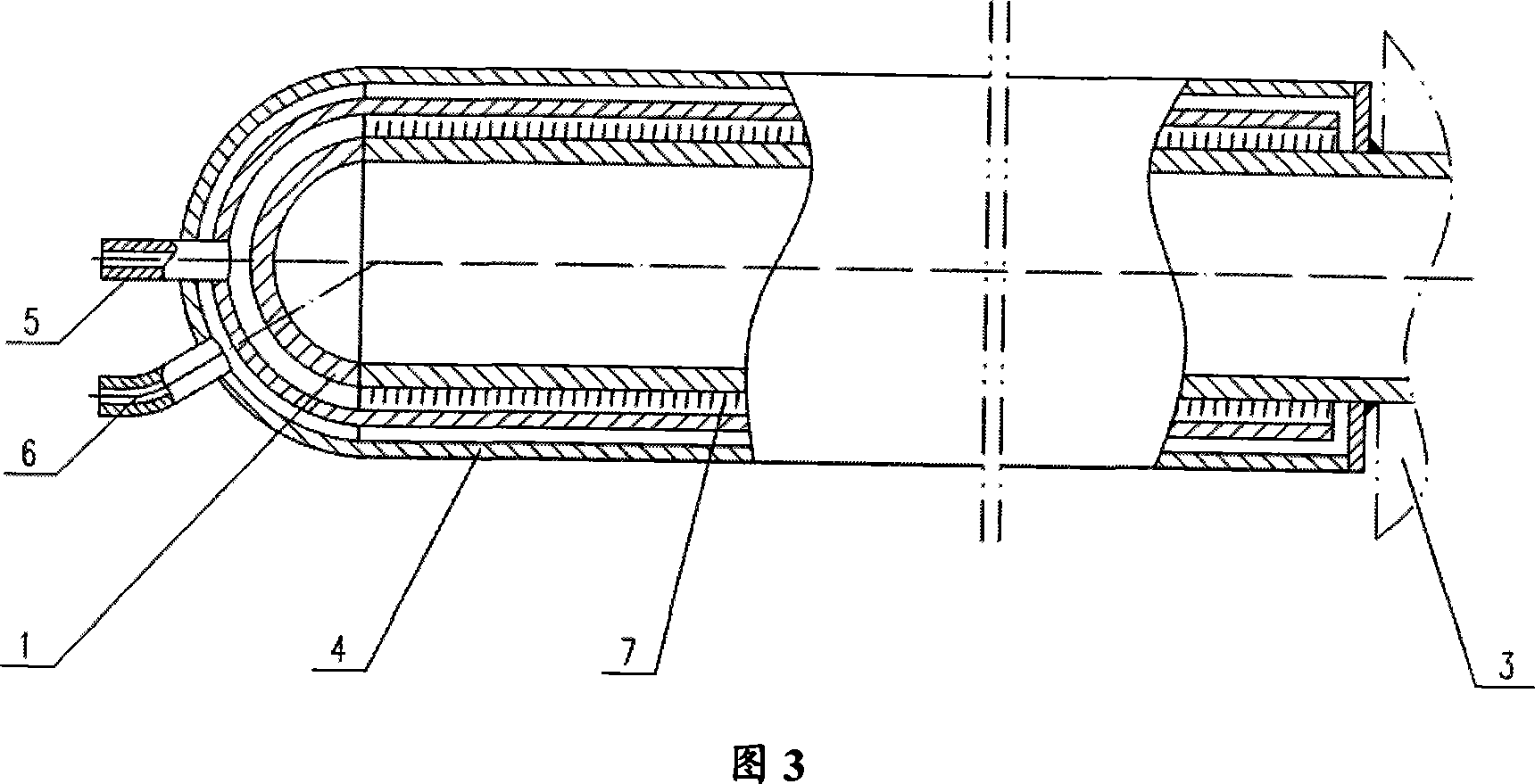
[0024] As shown in Figure 1, Figure 2, and Figure 3, the high-temperature solar heat pipe receiver structure for dish solar thermal power generation includes several special-shaped high-temperature heat pipes 1, and a heat-absorbing cavity 2 formed by high-temperature heat pipes 1 evenly distributed in the middle, The high-temperature heat pipe 1 is divided into a ceramic cone 3 of a heat absorbing section and a heat releasing section, a sleeve 4 for heat exchange of a working fluid, a working fluid inlet pipe 5 and a working fluid outlet pipe 6 . The part of the high-temperature heat pipe 1 in the casing 4 is cylindrical, while the part in the heat-absorbing cavity is processed into a shuttle shape and connected in pairs. Spiral fins 7 are installed on the outer wall of the heat release section of the high-temperature heat pipe 1 in the casing 4 to enhance the heat exchange of the fluid. The opening of the heat-absorbing cavity is provided with a lighting hole 8 made of ceram...


PUM


Abstract

The invention relates to a high-temperature solar energy receiver. The invention has a structure that heat absorbing sections of each neighboring different-shape high-temperature heat tube are connected two by two and equally arranged to form a heat absorbing cavity; the heat absorbing section of the different-shape high-temperature heat tube takes a shape of shuttle; a bushing is sleeved with a heating section of the different-shape high-temperature heat tube, and a work liquid inlet and a work liquid outlet are arranged on the bushing. The invention solves the defects that the heat absorbing efficiency is low and the use is limited, etc. The invention is provided with the different-shape high-temperature heat tube which is reconstructed on the basis of a column-shaped high-temperature heat tube as the heat absorbing and transmission component, with an easy manufacturing process and low manufacturing cost. Although the heat absorbing sections of each heat tube are mutually connected, the work is comparatively independent and a local failure has no impact on the whole receiver, with high reliability. The heat absorbing cavity is provided with the shuttle, triangle and ellipse, etc. parts which is suitable for receiving incidence light, and then the heat absorbing efficiency is enhanced. No clearance exists in the middle of the high-temperature heat tubes mutually connected in the heat absorbing section so as to prevent incidence light loss and enhance the efficiency of the whole receiver.

Description

technical field [0001] The invention relates to a heat pipe receiver, in particular to a high-temperature solar receiver. Background technique [0002] Dish solar thermal power generation technology gathers solar radiation into a receiver through a parabolic dish concentrator, and the receiver absorbs the energy and transmits it to a thermoelectric conversion system, thereby realizing the conversion of solar energy into electrical energy. Due to its high efficiency and suitability for building distributed energy systems, the dish system has been developed to a certain extent. The receiver is the core component of the dish solar thermal power generation system, which directly determines the efficiency and reliability of the whole system, so it has received people's attention. [0003] There are two types of receivers for dish solar thermal power generation systems: direct irradiation and indirect heating. The former concentrates the sunlight and directly shines on the heat ...

Claims


Application Information

Patent Timeline
Patent Type & Authority Applications(China)
IPC IPC(8): F24J2/32F24J2/46F24S10/95
CPCY02E10/44
Inventor 张红许辉白穜丁莉陈兴元陶汉中庄骏
Owner NANJING UNIV OF TECH
Why Eureka
Try Eureka