H-bridge inverter of AC motor

A technology of AC motors and inverters, which is applied in the direction of AC motor control, intermediate conversion to DC conversion equipment, conversion of AC power input to AC power output, etc., and can solve problems such as voltage increase and stop

Active Publication Date: 2008-05-14
LSIS CO LTD
View PDF0 Cites 14 Cited by
  • Summary
  • Abstract
  • Description
  • Claims
  • Application Information

AI Technical Summary

Problems solved by technology

[0012] However, problems still occur because if the circuit breaker connected to the power unit of one phase is tripped, the voltage applied to the p

Method used


Image

  • H-bridge inverter of AC motor
  • H-bridge inverter of AC motor
  • H-bridge inverter of AC motor

Examples


Embodiment Construction

[0026] Reference will now be made in detail to the preferred embodiments of the invention, examples of which are illustrated in the accompanying drawings.

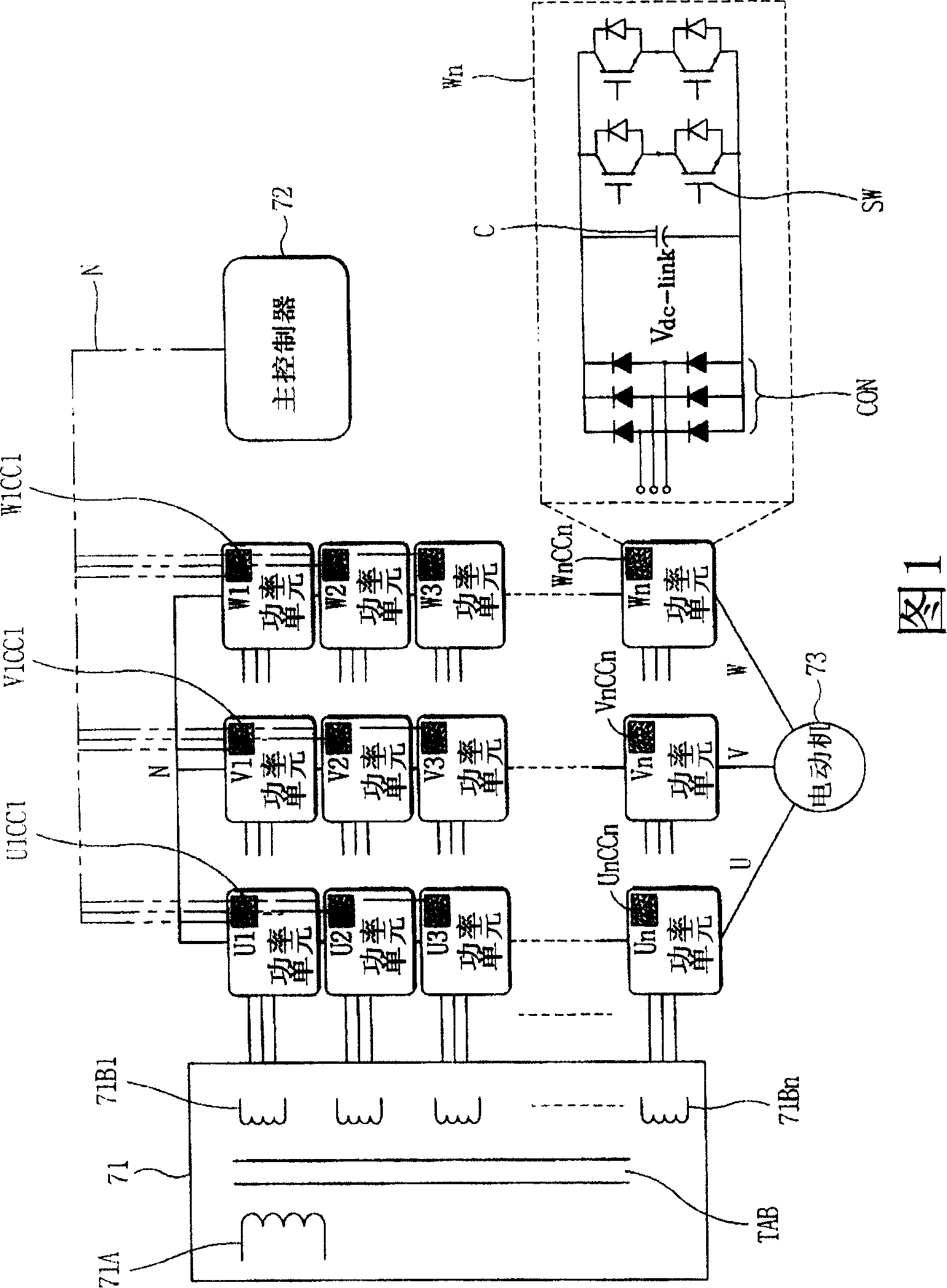
[0027] FIG. 1 is a block diagram showing the entire structure of an H-bridge inverter for an AC motor according to the present invention.

[0028] As shown in FIG. 1 , the H-bridge inverter for an AC motor according to the present invention includes a phase-shifting transformer 71 .

[0029] The phase shift transformer 71 includes a primary coil 71A and a plurality of secondary coils 71B1 to 71Bn. The primary coil 71A is formed of a three-phase delta coil receiving a three-phase AC power such as AC220V and a frequency of 60 Hz. The secondary coils 71B1˜71Bn convert, for example, the voltage of AC220V of the primary coil 71A to 24V and supply 24V to each of the power units U1˜Un, V1˜Vn, W1˜Wn, and are formed of triangular coils. TAB is a center tap located between the primary coil 71A and the secondary coils 71B1 to 71Bn....


PUM


Abstract

The invention discloses an H-bridge inverter which is applied to an alternating current motor and outputs an output voltage of a power cell by allowing a cell controller compensating the power cell with an input voltage even if the input voltage changes. Users can select an operation mode of every cell controller as a compensation mode which is applicable for the input voltage and as an output voltage control mode according to simple instruction frequency. The cell controller provides a compensation control function for changes of the input voltage, thereby reducing communication loads between a main controller and a cell controller.

Description

technical field [0001] The present invention relates to a drive control of an AC motor used as a drive power source for industrial high-power equipment such as pumps, fans, compressors, agitators and conveyors and requiring a high-voltage power source. [0002] In particular, the present invention relates to a high voltage inverter having an output voltage of 2 kilovolts (KV) to 5KV, and more particularly to a high voltage inverter capable of Each of the three phases (for example, an inverter with an output voltage of 200V or 400V) is connected in series to obtain a high output voltage. [0003] More particularly, the present invention relates to an inverter system capable of distributed control by a unit controller for individual control of each power unit and a master controller for controlling the unit controllers device. [0004] More particularly, the present invention relates to a high voltage inverter system in which the output voltage is not affected by variations in...

Claims


Application Information

Patent Timeline
IPC IPC(8): H02P27/06H02P27/08H02M5/44H02M5/458H02M7/5387H02M7/5395
Inventor 田在铉
Owner LSIS CO LTD
Why Eureka
Try Eureka