Engine braking methods and apparatus

A technology of engine braking and engine, which is applied in the direction of engine control, mechanical equipment, engine components, etc., and can solve the problems of engine positive power output and adverse effects of emissions, reducing the braking efficiency of the blower, reducing the engine, etc.

Inactive Publication Date: 2008-05-14
JACOBS VEHICLE SYST
View PDF4 Cites 11 Cited by
  • Summary
  • Abstract
  • Description
  • Claims
  • Application Information

AI Technical Summary

Problems solved by technology

These pockets can adversely affect the engine's positive power output and emissions
[0010] Accordingly, the present applicants have determined that the inclusion of a main exhaust event in a runaway type braking cycle would reduce the effectiveness of runaway braking and / or reduce the desire to equip the engine to achieve runaway braking

Method used


Image

  • Engine braking methods and apparatus
  • Engine braking methods and apparatus
  • Engine braking methods and apparatus

Examples


no. 1 approach

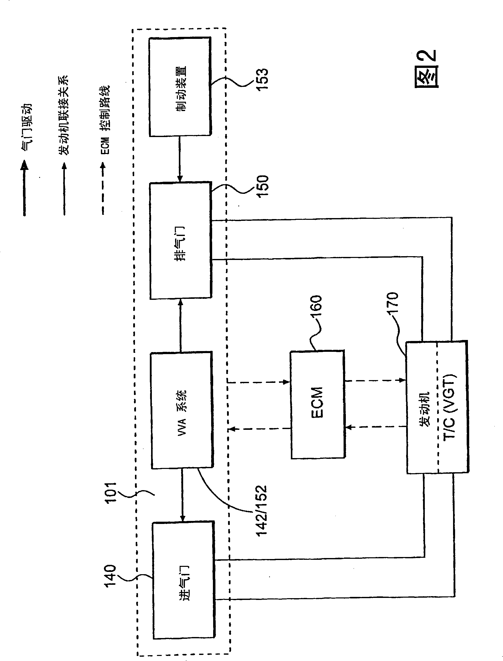
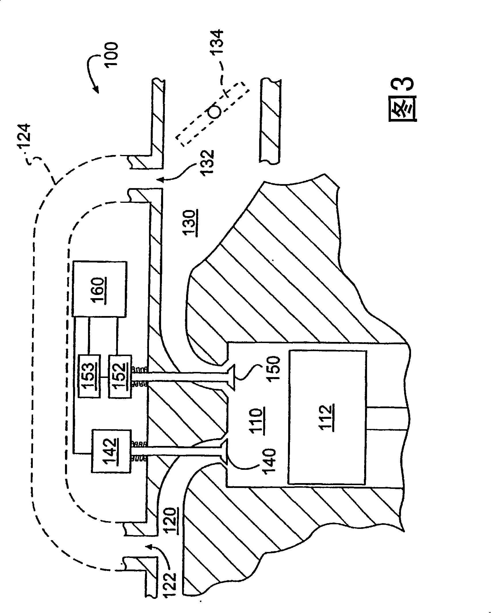
[0038] Reference will now be made in detail to a first embodiment of the system of the present invention, an example of which is represented in FIG. 2 . Valve actuation system 101 may include a VVA system 152 / 142 in operative communication with one or more intake valves 140 and one or more exhaust valves 150 . The VVA system may include two separate components 142, 152 dedicated to actuating the intake and exhaust valves, respectively, or the system may be a combined system. An engine braking device 153 may also be in operative connection with the exhaust valve 150 . In certain embodiments of the invention, particularly compression-release embodiments, the separate engine braking device 153 may be eliminated by integrating the engine braking function into the VVA system 152 / 142.

[0039] The valve actuation system 101 , particularly the VVA system 152 / 142 and the engine braking device 153 may be in operative connection with an ECM 160 . ECM 160 may send control signals t...


PUM


Abstract

The present invention discloses a method and apparatus for implementing blower type engine braking and compression-release type engine braking on an internal combustion engine. With blower-type engine braking, the exhaust valve is held at a relatively constant low lift during all or most of the engine's operating cycle. Engine braking may be combined with operation of exhaust gas recirculation, variable exhaust brake operation, and / or operation of a variable geometry turbocharger.

Description

technical field [0001] This application is related to, and enjoys prior filing date and priority to, U.S. Provisional Patent Application No. 60 / 435,295, filed December 23, 2002, entitled "Engine Braking Method and equipment". [0002] The invention relates to a method and a device for performing braking of an internal combustion engine. More specifically, the present invention relates to techniques for braking an engine by controlling the flow of exhaust gas through the engine. Background technique [0003] Engine braking systems have been around for many years. Such systems are particularly suitable for heavy vehicles, such as trucks and buses, since these vehicles have high braking requirements and typically use diesel engines. The reason diesel vehicles require an engine braking system is that there is an inherent gas-intake phenomenon in the cylinder due to the timing of the valves (main intake event and main exhaust event), where the valve timing operation is the eng...

Claims


Application Information

Patent Timeline
Patent Type & Authority Applications(China)
IPC IPC(8): F02D9/06F02D13/02F02B69/06F01L13/06F02D13/04F01L1/08F01L1/18F01L1/26F01L1/34F01L9/10F01L9/11F01L9/20F02B3/06F02D23/00F02M25/07
CPCF02M25/0752F02M25/0715F01L1/34F01L1/181F01L9/02F02D13/04F01L1/08F02D13/0207F01L13/06F02B3/06F01L1/267F01L13/065F02D13/0246F01L2105/00F01L9/021F01L2001/34446F02D9/06F01L9/04F02D23/00Y02T10/121F01L2760/004F01L2800/00F02D13/0273F02M26/13F02M26/01F01L2305/00F01L9/11F01L9/10F01L9/20
Inventor 杨周
Owner JACOBS VEHICLE SYST
Why Eureka
Try Eureka