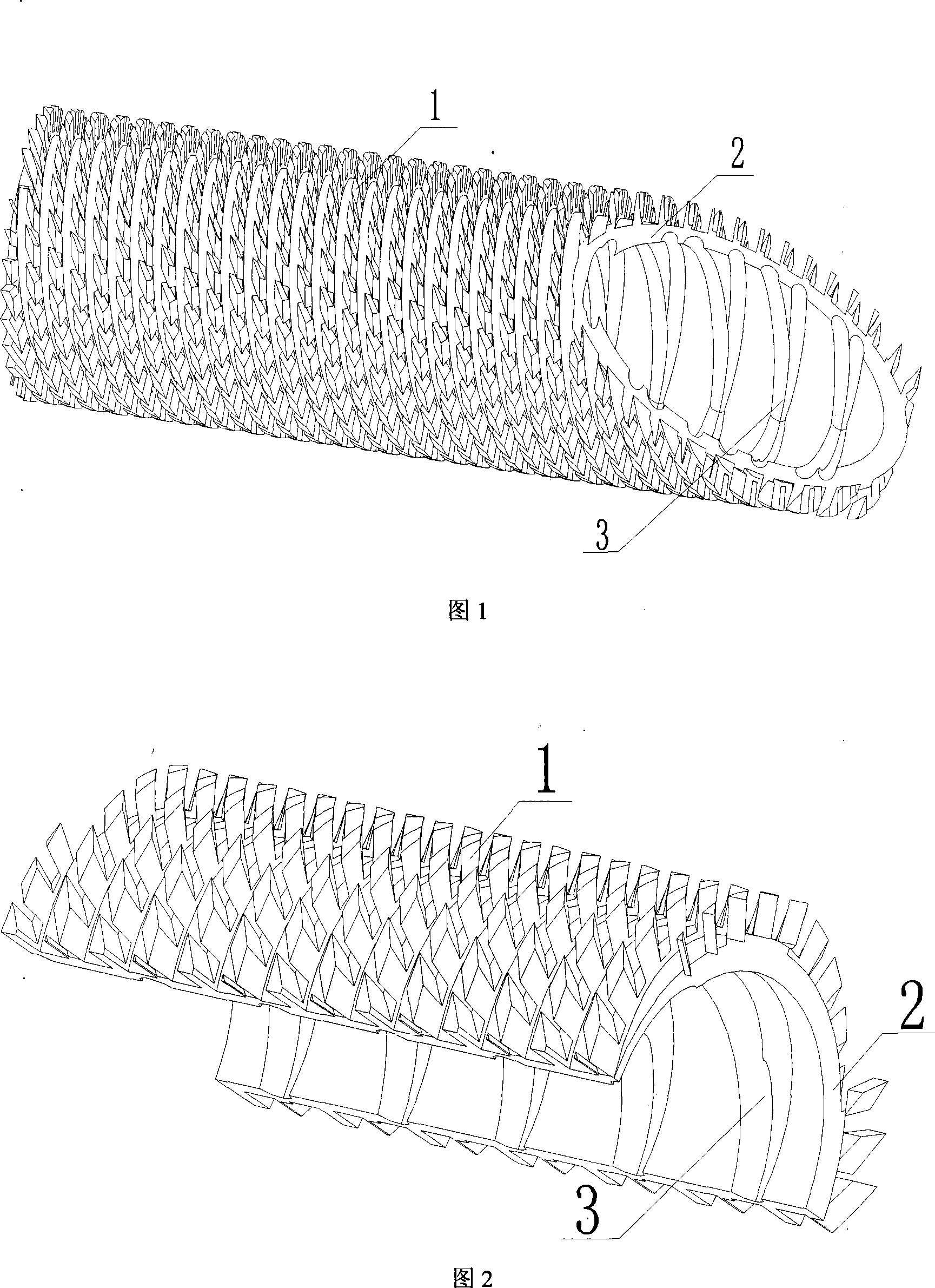
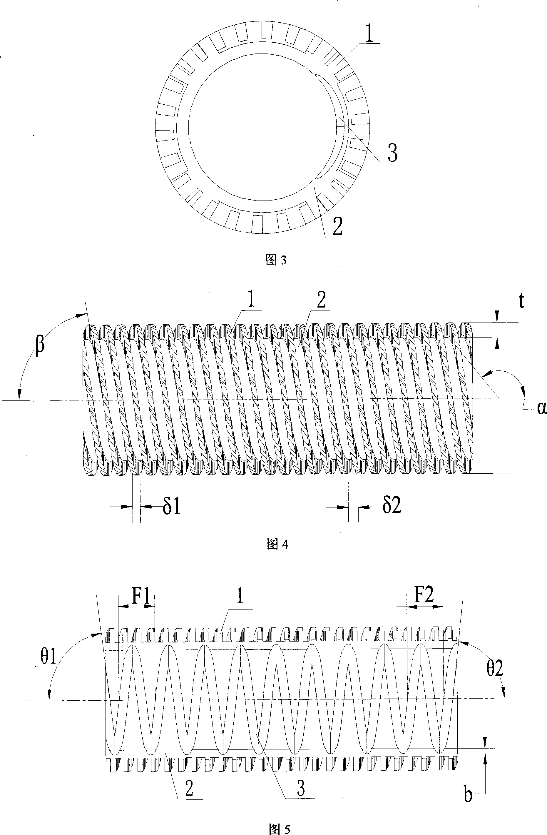
Inner chiasma spiral exterior three-dimensional diamond-type rib double-side intensify heat transfer pipe

A heat transfer tube and internal spiral technology is applied in the field of strengthening heat transfer tubes, which can solve the problems of inability to take into account the heat transfer effect inside and outside the tube, poor anti-scaling and anti-scaling functions, and large consumption of metal plates, so as to increase anti-scaling and anti-scaling. capacity, maintaining heat transfer performance, compact structure

Inactive Publication Date: 2008-05-21
SOUTH CHINA UNIV OF TECH
View PDF1 Cites 17 Cited by
  • Summary
  • Abstract
  • Description
  • Claims
  • Application Information

AI Technical Summary

Benefits of technology

This patented technology solves problems such as poor conductions caused by insufficient cooling during operation due to lack of sufficient airflow around certain parts of the tubular body's surface where temperature rises quickly when compared against other areas within the tire. By incorporating these technical features like helix shaped ridges along its outer edge, spiraling groovcks between them, and crossing spirals in the channel walls, this design enhances consistency and efficiency in conductance heat transmission while reducing impediment from surrounding regions. Additionally, adding multiple layers of triangular pyramid shape elements further increases heat transfer without compromising any desired properties (such as prevention of stalling). Overall, this new type of tube design provides improved heat dissipative capabilities at both inner and external surfaces.

Problems solved by technology

The technical problem addressed in this patented technology relates to improving heat transmission within heat exchanges without increasing their size due to enlargement of components like pipings and reducing friction between parts during operation.

Method used


Image

  • Inner chiasma spiral exterior three-dimensional diamond-type rib double-side intensify heat transfer pipe
  • Inner chiasma spiral exterior three-dimensional diamond-type rib double-side intensify heat transfer pipe

Examples


Embodiment

[0045] Now take the transformation of the oil cooler in thermal power plant as an example to illustrate the effect of the present invention:

[0046] The heat transfer efficiency of the copper smooth tube oil cooler in a power plant is low, which makes it impossible to cool the oil temperature to a given value, causing related equipment to malfunction and affecting the normal operation of the power plant. The present invention is now manufactured with steel pipes, and the structural parameters are as the above-mentioned specific examples of the present invention to replace the original copper pipes in the oil cooler for copper-free transformation.

[0047] After modification, under the same working condition, the total heat transfer coefficient of the oil cooler of the invention is 28%-54% higher than that of the copper smooth tube oil cooler. This shows that although the thermal conductivity of the steel pipe is less than half of that of the copper pipe, the total heat transf...


PUM


Abstract

The invention discloses an internal crossing external spiral three-dimensional rhombus rib dual-side strengthening heat transfer tube and comprises a base body of the heat transfer tube, a rhombus rib outside the tube and a spiral groove in the tube. The base body of the heat transfer tube, the rhombus rib outside the tube and the spiral groove in the tube are integrated into a whole and the rhombus rib outside the tubes are disconnected with each other and are distributed in a spiral way along the axial direction to form a three-dimensional expanding surface on the whole external surface of the tube wall; the spiral groove are distributed in the base body of the heat transfer tube in a cross way and are presented in pairs along the direction of turning on the left and the right side. With the three-dimensional rhombus rib out of the tube, the invention increases heat transfer area while damaging a stagnant boundary layer and improving the convective heat transfer coefficient and the condensation heat transfer coefficient, meanwhile, the spiral groove cross-distributed in the tube can induce second separation flow and promote the intensification of turbulent extent while improving the convective heat transfer coefficient in the tube and increasing the capability of scale resistance. In addition, the invention has wide application range and compact structure as well as metal material saving under the same condition of heat transfer.

Description


Claims


Application Information

Patent Timeline
Owner SOUTH CHINA UNIV OF TECH
Why Eureka
Try Eureka