
Embedded system remote upgrade method for repeater equipment

An embedded system, remote upgrade technology, applied in radio relay systems, network data management, electrical components, etc., can solve the problems of trouble and inconvenience, difficult upgrade work, high upgrade cost, and improve upgrade efficiency and easy version. Management, the effect of reducing upgrade costs

Inactive Publication Date: 2008-05-21
SHENZHEN GRENTECH CO LTD
View PDF0 Cites 32 Cited by
  • Summary
  • Abstract
  • Description
  • Claims
  • Application Information

AI Technical Summary

Problems solved by technology

[0005] 1. The efficiency of software upgrade is low, the upgrade cost is high, and batch upgrade cannot be realized. On the one hand, the installation locations of repeater equipment are distributed in a wide range, and they are all over various areas with poor signal quality. The monitoring software of repeater stations within a certain range When upgrading, there are usually two solutions: ① configure a small number of personnel, and upgrade the sites one by one; ② configure a large number of personnel, and upgrade all sites at the same time
The difference between these two methods is that the cost is generally high. On the other hand, the installation location of the repeater equipment is generally difficult to reach, such as on the transmission tower on the top of the mountain or in the weak electric well in the basement, which will cause certain difficulties for the upgrade work.
Finally, because it is a decentralized upgrade, batch upgrades cannot be realized;
[0006] 2. Due to the limitation of on-site resource conditions for upgrade operations, on-site resources for repeater installation are usually relatively scarce, such as power supplies, signal lines, etc. If these resources are not available, on-site upgrades cannot be carried out smoothly;
[0007] 3. Once the monitoring software upgrade fails, the monitoring board cannot automatically restore to the original version. The monitoring software upgrade adopts overlay upgrade, and the new version of the software directly overwrites the old version of the software, so the new version of the software cannot automatically restore to the old version after an error occurs. re-upgrade;
[0008] 4. It is difficult to control and trace back the upgrade version of the monitoring software. The monitoring software is upgraded in a distributed manner. The software versions released by each site may be different, and the versions cannot be managed uniformly. The monitoring software upgrade package is brought to the site by the maintenance personnel for upgrade. monitoring and control;
[0009] 5. The quality level of maintenance personnel is required to be high, and each repeater is widely distributed, and a large number of maintenance personnel is also required, which greatly increases the upgrade cost
[0010] The above-mentioned existing upgrade methods cause trouble and inconvenience when used, and need to be improved.

Method used

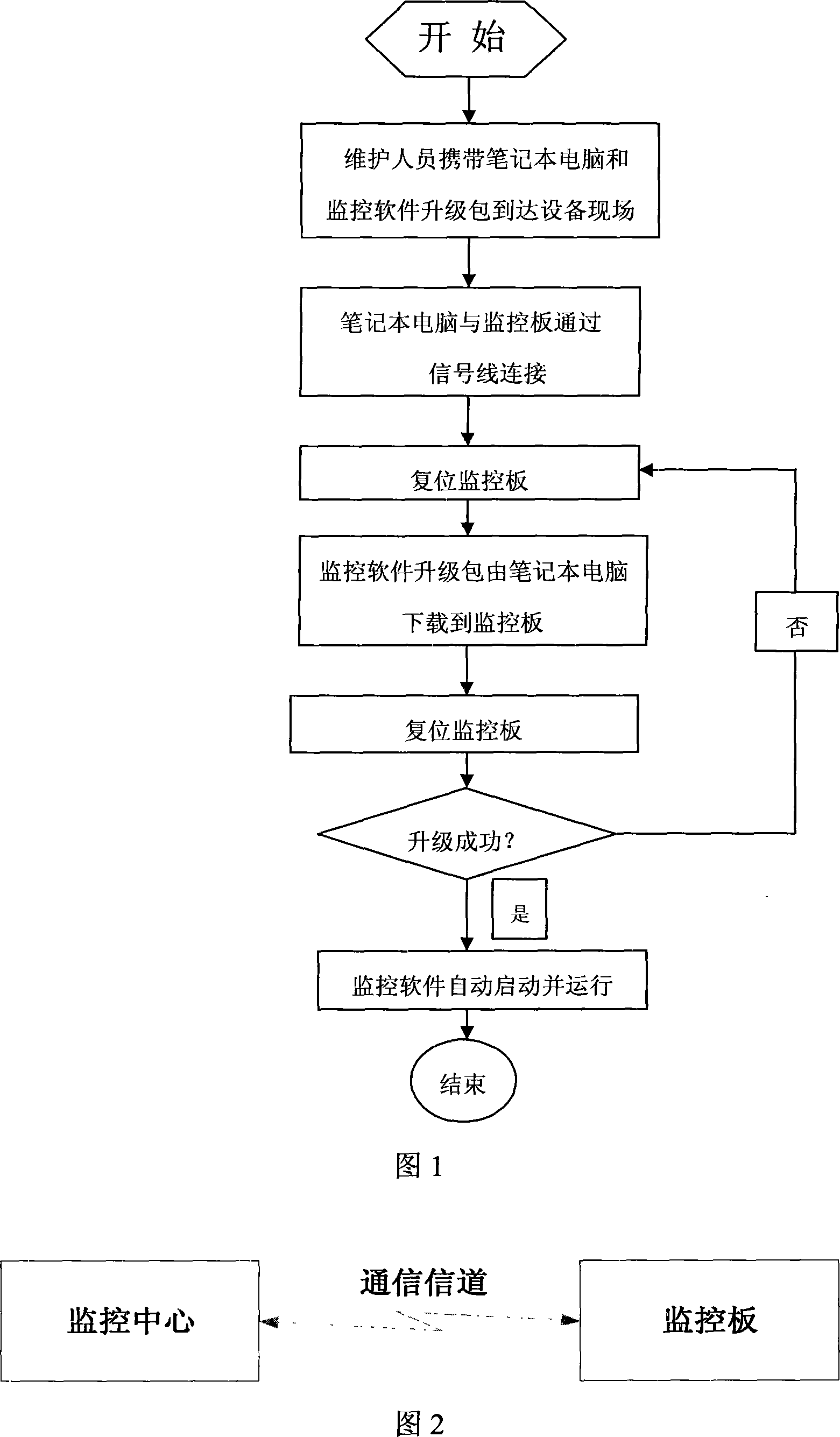
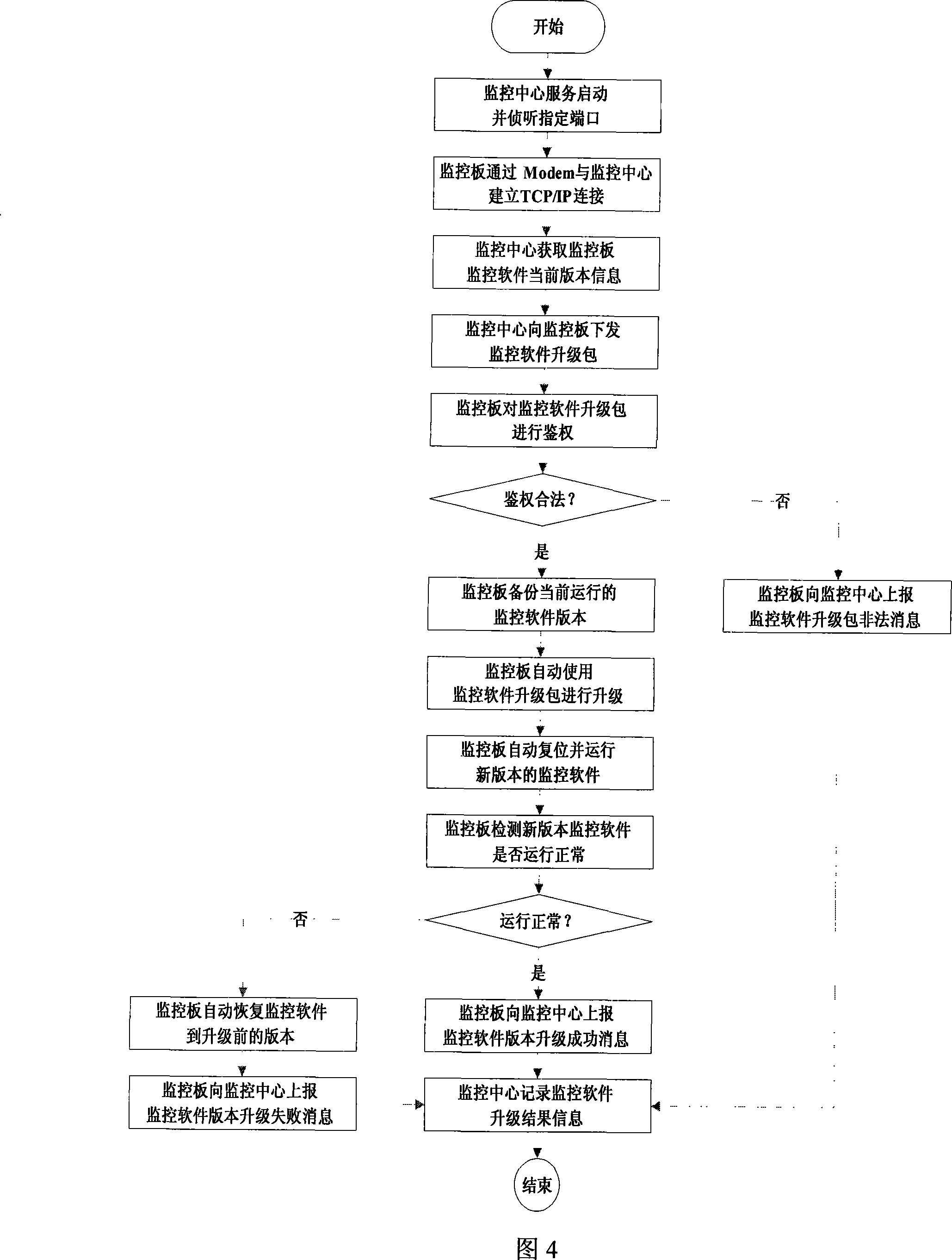

Image

  • Embedded system remote upgrade method for repeater equipment
  • Embedded system remote upgrade method for repeater equipment
  • Embedded system remote upgrade method for repeater equipment

Examples


no. 1 example G

[0046] [The first embodiment GPRS remote connection mode]

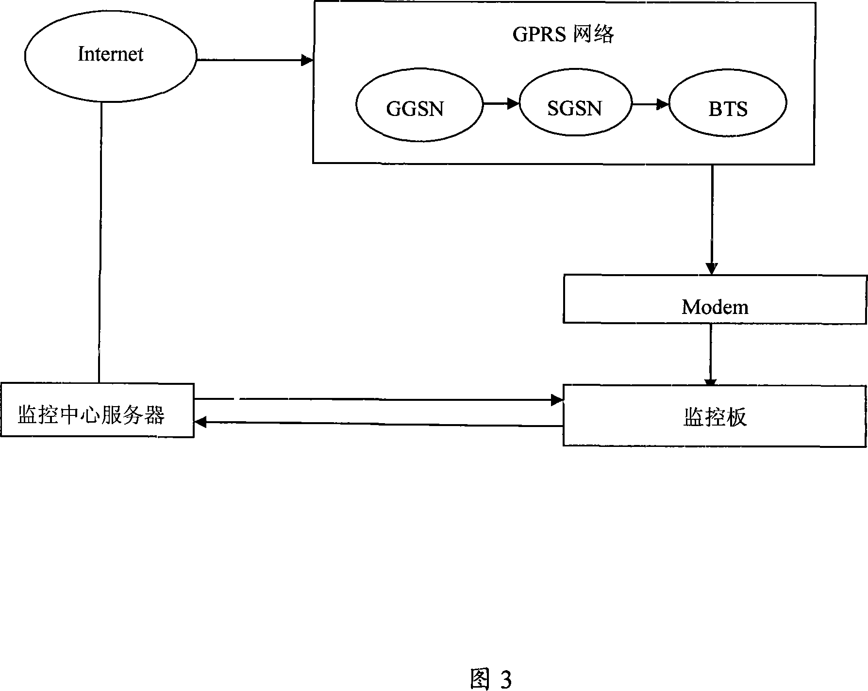
[0047] As shown in FIG. 3 , it is a network structure diagram of this embodiment.

[0048] The network structure includes a monitoring center terminal and a monitoring board, and a wireless connection is used between the two, specifically, a GPRS remote connection is used.

[0049] The monitoring center end is connected to the Internet through a fixed network, used for a fixed public IP address, and starts a network service to listen to a designated port.

[0050] The monitoring board dials to the GPRS network through the Modem, obtains the dynamic IP address assigned by the network, and then uses the same port used in the monitoring center to establish a TCP / IP connection with the monitoring center server.

[0051] In the case of adopting this network structure, the monitoring center can only listen to the designated port passively, waiting for the monitoring board to actively connect. Before the monitoring board is ...

no. 2 example

[0074] [Second embodiment PSTN remote connection mode]

[0075] As shown in FIG. 5 , it is a network structure diagram of the second embodiment of the present invention.

[0076] The network structure includes the monitoring center terminal and the monitoring board, and the connection between the two is established through a wired Modem. Specifically, the monitoring board establishes a data transmission connection with the PSTN Model of the monitoring center through the PSTN Modem. In the case of adopting this networking structure, both ends of the monitoring center and the monitoring board can actively initiate a dial-up connection, and the connected end is responsible for authenticating the connection information of the connecting end, accepting legal connections, and disconnecting illegal connections.

[0077] In view of the characteristics of PSTN network application, in order to avoid unnecessary occupation of PSTN network resources, the monitoring center and monitoring ...


PUM


Abstract

The invention discloses a remote upgrading method for a repeater embedded system, which comprises the following four steps: step one, a remote connection is formed between a monitor board and a monitor center; step two, a monitor software upgrading packet is sent to the monitor board from the monitor center; step three, a backup of the current monitor software edition is made by the monitor board; step four, the monitor software upgrading packet is used by the monitor board to proceed the upgrading. The invention has the advantages that: batch upgrading is completed uniformly; remote centralized upgrading for a plurality of stations is realized; the upgrading efficiency is improved; the upgrading cost is reduced; the method of upload resume is adopted; the whole monitor software upgrading process can be controlled; the success rate of upgrading is improved; the management of the monitor software edition at the station can be easily realized; edition tracing and tracking are provided; the previous edition can be ensured to run normally when software upgrading fails.

Description

【Technical field】 [0001] The invention relates to the field of software upgrading of repeater equipment, in particular to a remote upgrading method for an embedded system of a repeater. 【Background technique】 [0002] In the field of wireless communication, large-scale radio frequency signal coverage is usually completed by the base station, but in practical applications, there are also areas where the base station signal cannot be covered or the signal effect is not good. This area is called a "blind area". The repeater is the network optimization equipment to eliminate the "blind area" of this wireless signal. The repeater collects the radio frequency signal from the base station, and then transmits the radio frequency signal to the "blind area" after necessary amplification to achieve the purpose of eliminating the "blind area". . [0003] With the complexity of the wireless environment, the expansion of coverage and the diversity of coverage requirements, in order to ma...

Claims


Application Information

Patent Timeline
IPC IPC(8): H04Q7/34H04Q7/22H04B7/14H04W8/24H04W24/02H04W88/04
Inventor 郑建辉吴斌陆开怀
Owner SHENZHEN GRENTECH CO LTD
Learn More