Power transmission device, and display device and display panel pedestal that have the power transmission device

A technology of power transmission device and display panel, applied in the direction of transmission device, transmission device parts, gear transmission device, etc., can solve the problems of different torque, difference in the quality of rotating objects, adjusting the reduction ratio of the reducer, etc., to eliminate the backlash Effect

Inactive Publication Date: 2010-12-29
PANASONIC CORP
View PDF4 Cites 0 Cited by
  • Summary
  • Abstract
  • Description
  • Claims
  • Application Information

AI Technical Summary

Problems solved by technology

[0034] However, even if the motors are produced with the same specifications, there are differences in the characteristics of the motors, so the torque generated by the motor 108 and the motor 109 may be different.
In this case, the load torque acting on the output shaft 103 is no longer as designed, so the tooth surface contact between the transmission gear and the output gear will be cut off halfway, and the backlash cannot be eliminated.
[0035] In addition, although the load torque is set according to the mass of the rotating object attached to the output shaft 103, the mass of the rotating object may vary.
Therefore, due to this difference, it may sometimes happen that the load torque applied to the output shaft 103 is not as designed, so that the backlash cannot be eliminated.
[0036] Furthermore, in the backlash-free power transmission device 1801, it is difficult to adjust the reduction ratio of each speed reducer according to the above-mentioned difference so that the designed load torque acts on the output shaft 103

Method used


Image

  • Power transmission device, and display device and display panel pedestal that have the power transmission device
  • Power transmission device, and display device and display panel pedestal that have the power transmission device
  • Power transmission device, and display device and display panel pedestal that have the power transmission device

Examples


Embodiment approach 1

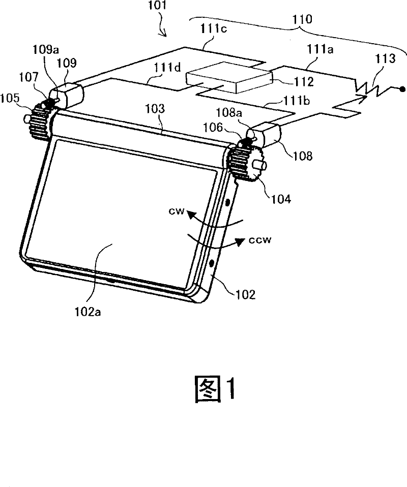
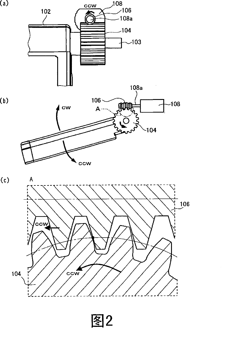
[0077] First, the configuration of a power transmission device and a display device using the same in Embodiment 1 of the present invention will be described with reference to FIGS. 1 and 2 . FIG. 1 is a perspective view showing the configuration of a power transmission device and a display device in Embodiment 1 of the present invention. Fig. 2 is a diagram showing the meshing state of the transmission gear and the output gear in the power transmission device shown in Fig. 1, Fig. 2 (a) is a front view viewed from a direction perpendicular to the output shaft of the power transmission device, Fig. 2 (b ) is a side view viewed from the axial direction of the output shaft of the power transmission device, and FIG. 2( c ) is a cross-sectional view showing a section of part A shown in FIG. 2( b ).

[0078] As shown in FIG. 1 , the display device in the first embodiment includes the power transmission device 101 and the display panel 102 in the first embodiment. In addition, the ...

Embodiment approach 2

[0119] Next, the structure of a power transmission device according to Embodiment 2 of the present invention and a display device using the same will be described with reference to FIGS. 7 and 8 . 7 is a perspective view showing a schematic configuration of a power transmission device and a display device according to Embodiment 2 of the present invention. FIG. 8 is an enlarged view of a part of the power transmission device shown in FIG. 7, FIG. 8(a) is a diagram showing the installation portion of the torsion coil spring 605, and FIG. 8(b) is a diagram showing the installation portion of the torsion coil spring 604. picture.

[0120] Among the constituent elements shown in FIG. 7 , the constituent elements that are the same as the constituent elements used in Embodiment 1 and shown in the drawings are given the same reference numerals as those used in Embodiment 1. In FIG. Furthermore, in the following description, description of the same constituent elements as those shown...

Embodiment approach 3

[0151] Next, configurations of a power transmission device according to Embodiment 3 of the present invention and a display device using the same will be described with reference to FIGS. 12 to 15 . 12 is a perspective view showing a schematic configuration of a power transmission device and a display device in Embodiment 3 of the present invention. 13 is an enlarged perspective view of a part of the power transmission device shown in FIG. 12 , FIG.

[0152] Fig. 14 is a diagram showing the positional relationship between the blades provided on the output shaft shown in Fig. 12 and the blades provided on the rotary switch. 15( a ) is a circuit diagram showing a control circuit of the power transmission device shown in FIG. 12 , and FIG. 15( b ) is a diagram showing switching combinations of the rotary switches shown in FIG. 15( a ).

[0153] Components shown in FIGS. 12 to 17 that are the same as components used in Embodiments 1 and 2 and shown in the drawings are assigned th...


PUM


Abstract

Provided are a power transmission device where torque to be applied to an output shaft can be easily adjusted and a backlash between gears can be reliably removed, and a display device and a display panel pedestal that are provided with the power transmission device. The power transmission device (101) has a display panel (102), an output shaft (103) to which the display panel is connected, output gears (104, 105) rotated integrally with the output shaft, transmission gears (106, 107) meshing with the output gears, motors (108, 109) for applying driving force to the transmission gears, and a control circuit (110) for controlling the motors. The control circuit (110) causes the motors (108, 109) to drive the transmission gears (106, 107) at different rotation speeds to transmit different magnitudes of driving force to the output gears (104, 105). The output shaft (103) receives, besides torque in the direction of rotation of the shaft, torque in the opposite direction to the rotation direction of the shaft, and this suppresses occurrence of play caused by a change in the direction of torque produced by the weight of the display panel (102) it self.

Description

technical field [0001] The present invention relates to a power transmission device, a display device equipped with the same, and a base for a display panel. Looseness developed on the output shaft. Background technique [0002] Hereinafter, an example of a conventional power transmission device in which an object having its own weight is attached to an output shaft will be described with reference to FIGS. 19 to 22 . Fig. 19 is a perspective view showing an example of a conventional power transmission device. In the example shown in FIG. 19 , a power transmission device 1501 transmits power to a vehicle-mounted display panel (liquid crystal display panel) 102 provided on a ceiling surface of an automobile (not shown). [0003] As shown in FIG. 19 , the power transmission device 1501 is mainly composed of a display panel 102 , an output shaft 103 on which the display panel 102 is attached, a motor 108 for rotating the output shaft 103 , and a power supply unit 1503 for sup...

Claims


Application Information

Patent Timeline
Patent Type & Authority Patents(China)
IPC IPC(8): F16H1/16F16H57/12B60R11/02
CPCB60R2011/0028F16H1/16B60R2011/0085B60R2011/0092B60R2011/0082F16H57/12F16H2057/122B60R11/0235
Inventor 川副嘉郎表迫畅也田边直竹村基
Owner PANASONIC CORP
Why Eureka
Try Eureka