Method of depositing hafnium silicate assisted by catalyst

一种沉积方法、催化剂的技术,应用在金属材料涂层工艺、气态化学镀覆、涂层等方向

Inactive Publication Date: 2008-05-28
APPLIED MATERIALS INC
View PDF2 Cites 2 Cited by
  • Summary
  • Abstract
  • Description
  • Claims
  • Application Information

AI Technical Summary

Problems solved by technology

Oxidation sources present many challenges when depositing high-k silicates due to the reaction of the oxidation source with the catalyst

Method used


Image

  • Method of depositing hafnium silicate assisted by catalyst
  • Method of depositing hafnium silicate assisted by catalyst
  • Method of depositing hafnium silicate assisted by catalyst

Examples


Embodiment Construction

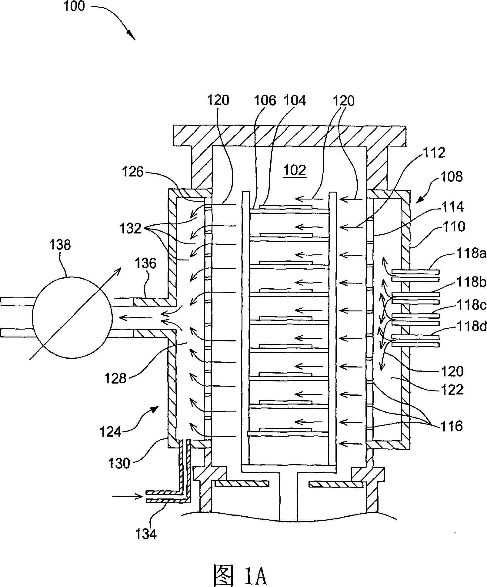
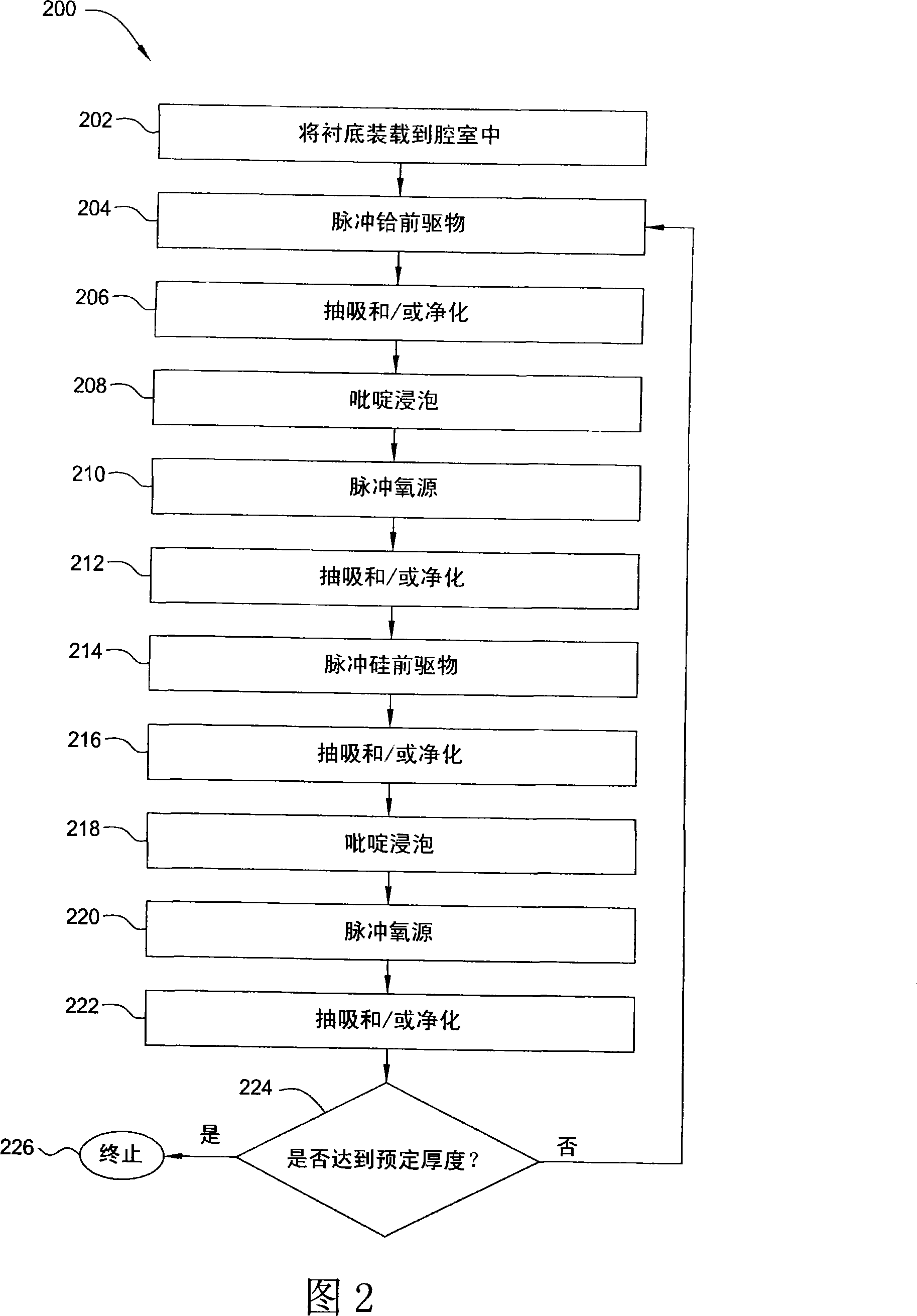
[0019] A hafnium silicate ALD method is described as an example of a high-k silicon method. To produce the hafnium silicate layer, the substrate may be exposed to pulses of hafnium precursors, pulses of oxidizing agents, pulses of silicon precursors, and pulses of other oxidizing agents. A siliconizing agent may additionally co-flow with one or more reactants into the chamber through a separate inlet. Alternatively, the siliconizing agent may flow into the chamber before the reactants are introduced into the soaking process. The hafnium silicate formation process can be performed rapidly and / or at low temperature by co-flowing with the catalyst through a separate inlet or by performing a catalyst soak.

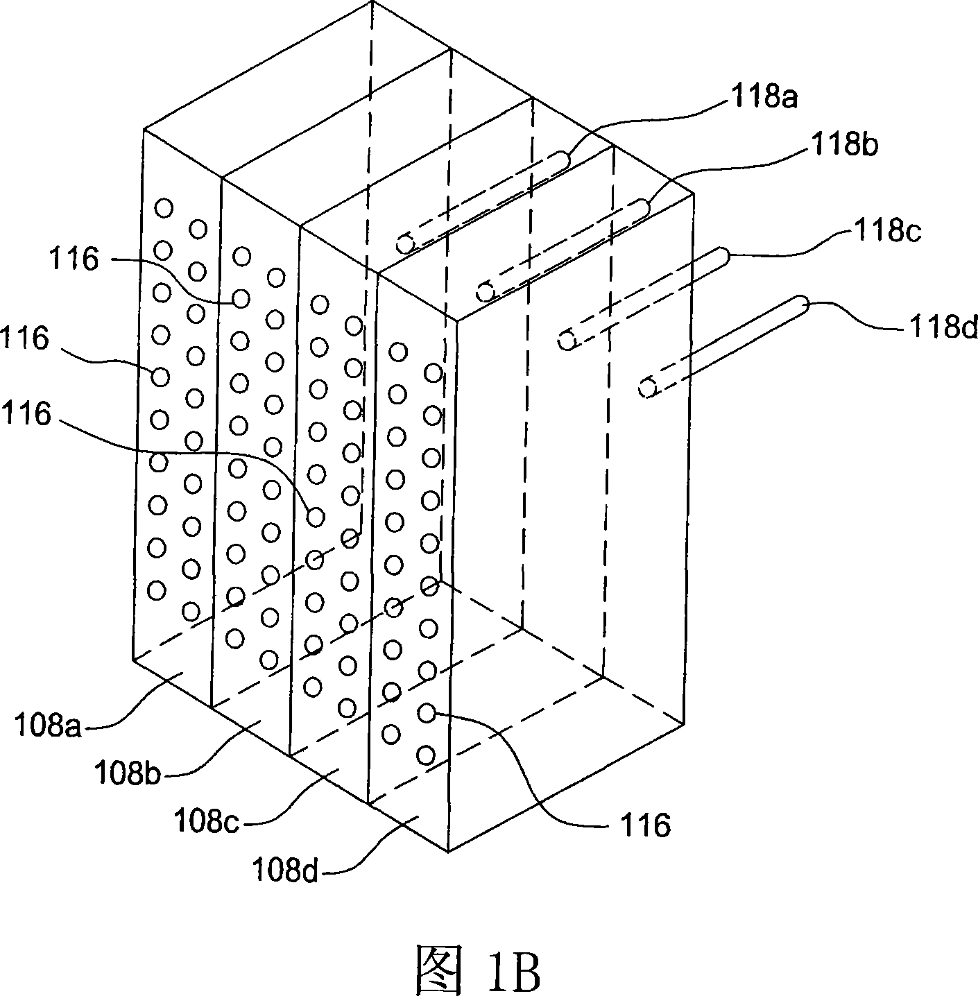
[0020] Figure 1A is a schematic view of an apparatus 100 according to one embodiment of the present invention. Apparatus 100 includes a vacuum chamber 102 . Apparatus 100 may be a batch processing apparatus 100 including one or more susceptors 106 upon which substrates 104 ...


PUM


Abstract

A high-k silicate atomic layer deposition method is disclosed. To produce a hafnium silicate layer, a substrate may be exposed to a pulse of a hafnium precursor, a pulse of an oxidizer, a pulse of a silicon precursor, and a pulse of another oxidizer. A catalyst may additionally be co-flowed with one or more reactants into the chamber through a separate inlet. Alternatively, the catalyst may be flowed to the chamber before the reactant is introduced in a soaking procedure. By either co-flowing the catalyst through separate inlets or by performing a catalyst soak, hafnium silicate formation may proceed at a fast rate and / or at a low temperature.

Description

technical field [0001] The present invention mainly relates to a method for depositing a hafnium silicate layer on a substrate by atomic layer deposition (ALD). Background technique [0002] In the field of semiconductor processing, flat panel display processing or other electronic device processing, vapor deposition processes play an important role in depositing materials onto substrates. As electronic device geometries continue to shrink and device densities continue to increase, feature size and aspect ratios become increasingly challenging. Therefore, conformal deposition of materials to form these devices is becoming increasingly important. [0003] While conventional chemical vapor deposition (CVD) has proven successful for device geometries and aspect ratios down to about 0.15 μm, more challenging device geometries require alternative deposition techniques. One technique that has attracted considerable attention is ALD. During an ALD process, reactive gases are seq...

Claims


Application Information

Patent Timeline
Patent Type & Authority Applications(China)
IPC IPC(8): C23C16/44C23C16/30
CPCC23C16/45525C23C16/45546C23C16/45534C23C16/401C23C16/52
Inventor 梅特伊·马哈贾尼
Owner APPLIED MATERIALS INC
Why Eureka
Try Eureka