Solenoid unit and method for producing said solenoid unit and a magnet housing for such a solenoid unit

A technology of electromagnetic device and shell, applied in the field of manufacturing such an electromagnetic device, and manufacturing a magnetic shell for such an electromagnetic device

Active Publication Date: 2008-05-28
BURKERT WERKE
View PDF1 Cites 9 Cited by
  • Summary
  • Abstract
  • Description
  • Claims
  • Application Information

AI Technical Summary

Problems solved by technology

Although this solenoid valve is suitable for operation with DC voltage, for cost reasons two valve structures are manufactured

Method used


Image

  • Solenoid unit and method for producing said solenoid unit and a magnet housing for such a solenoid unit
  • Solenoid unit and method for producing said solenoid unit and a magnet housing for such a solenoid unit
  • Solenoid unit and method for producing said solenoid unit and a magnet housing for such a solenoid unit

Examples


Embodiment Construction

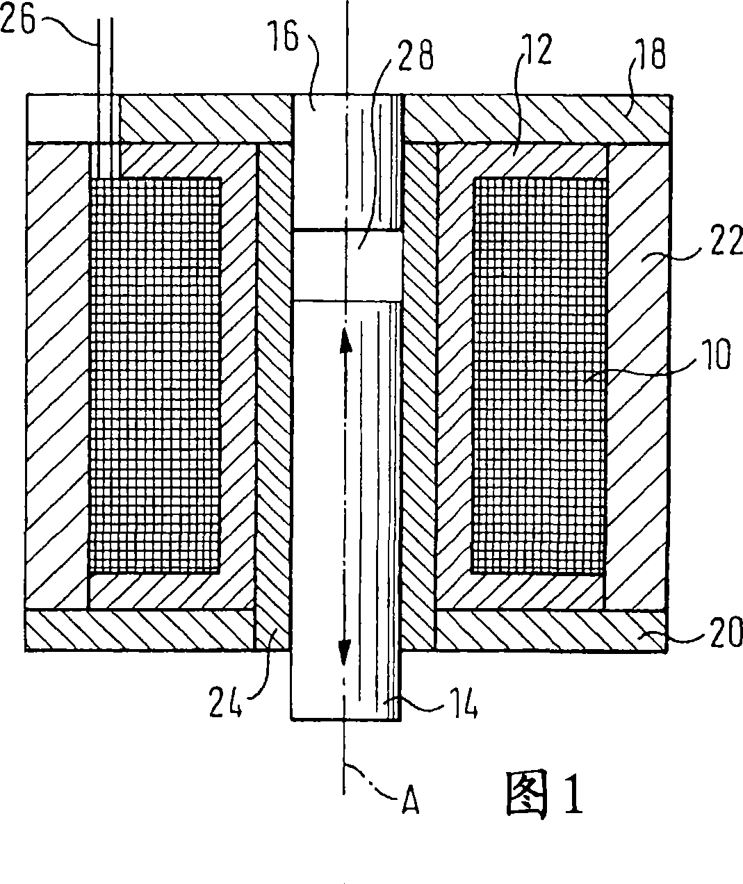
[0038] FIG. 1 shows a solenoid device for operating a solenoid valve, comprising a solenoid coil 10 , which defines a coil axis A and whose winding is accommodated by a coil former 12 . Furthermore, a ferromagnetic circuit is shown, which in FIG. 1 comprises a fixed magnet housing, a movable armature 14 and a fixed armature counterpole 16 . The magnet housing in this case has a top cover 18 , a bottom 20 and a housing 22 . Furthermore, a non-magnetic core guide 24 is provided, which extends within the magnetic coil 10 between the coil former 12 and the armature 14 or the armature counter-pole 16 . The power supply to the solenoid coil 10 takes place via the likewise schematically shown terminal 26 , which is led out axially.

[0039] On the solenoid coil 10 of the currentless switch, the armature 14 is usually loaded by a spring (not shown) in such a way that the solenoid valve is in a desired position (open or closed). When the solenoid coil 10 is powered, an axially adjust...


PUM

PropertyMeasurementUnit
thicknessaaaaaaaaaa

Abstract

An electromagnetic unit for a solenoid valve, has a magnetic coil and a ferromagnetic circuit surrounding the magnetic coil (10), which has a fixed magnet housing and a movable magnetic armature (14). The magnet housing is comprised of a cover (18), a wall (22) and a floor (20) in the form of multilayered transformer laminations. -

Description

technical field [0001] The invention relates to an electromagnetic device for an electromagnetic valve, comprising an electromagnetic coil and a ferromagnetic circuit surrounding the electromagnetic coil, which includes a fixed magnetic housing and a movable armature. Furthermore, the invention relates to a method for producing such an electromagnetic device and a method for producing a magnetic housing for such an electromagnetic device. Background technique [0002] Solenoid-actuated valves have a solenoid, an armature for opening and closing the valve, and a magnetic housing. In a simple design, the magnet housing is formed from a U-shaped bent solid plate. This design is preferably suitable for DC control. In alternating current control, this structural form produces a large number of eddy current losses. As a result, less effective power and magnetic force is available, taking into account the permissible heating. Furthermore, it is known, for example, from DE 19860...

Claims


Application Information

Patent Timeline
Patent Type & Authority Applications(China)
IPC IPC(8): H01F7/08H01F7/16H01F3/02
CPCH01F7/081H01F7/1607H01F2007/083
Inventor C·埃尔魏因
Owner BURKERT WERKE
Why Eureka
Try Eureka