Supercharge Your Innovation With Domain-Expert AI Agents!

Condenser microphone for smd using sealing pad and method of making the same

A technology of condenser microphones and microphones, applied in the direction of electrostatic transducer microphones, sensors, electrical components, etc., can solve the problems of reduced productivity and poor appearance, and achieve the effects of reduced defective rate, simplified manufacturing process, and low height

Inactive Publication Date: 2008-05-28
BSE CO LTD
View PDF0 Cites 2 Cited by
  • Summary
  • Abstract
  • Description
  • Claims
  • Application Information

AI Technical Summary

Problems solved by technology

[0010] However, if a liquid sealant is used for sealing, the liquid sealant permeates through the gap between the case and the PCB, causing defects due to contamination of components, lowering productivity due to the time required for curing, and distorting the appearance. Difference

Method used


Image

  • Condenser microphone for smd using sealing pad and method of making the same
  • Condenser microphone for smd using sealing pad and method of making the same
  • Condenser microphone for smd using sealing pad and method of making the same

Examples


no. 1 approach

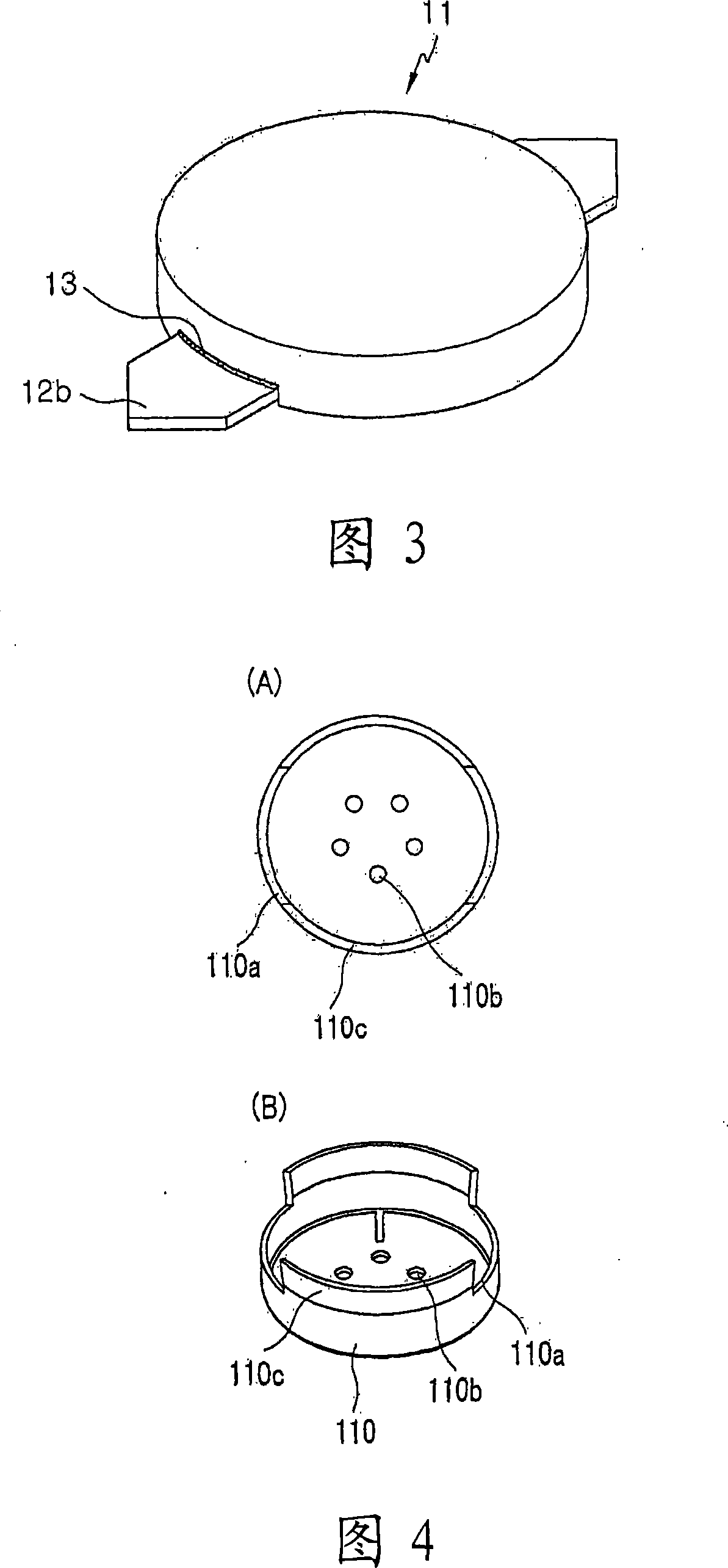
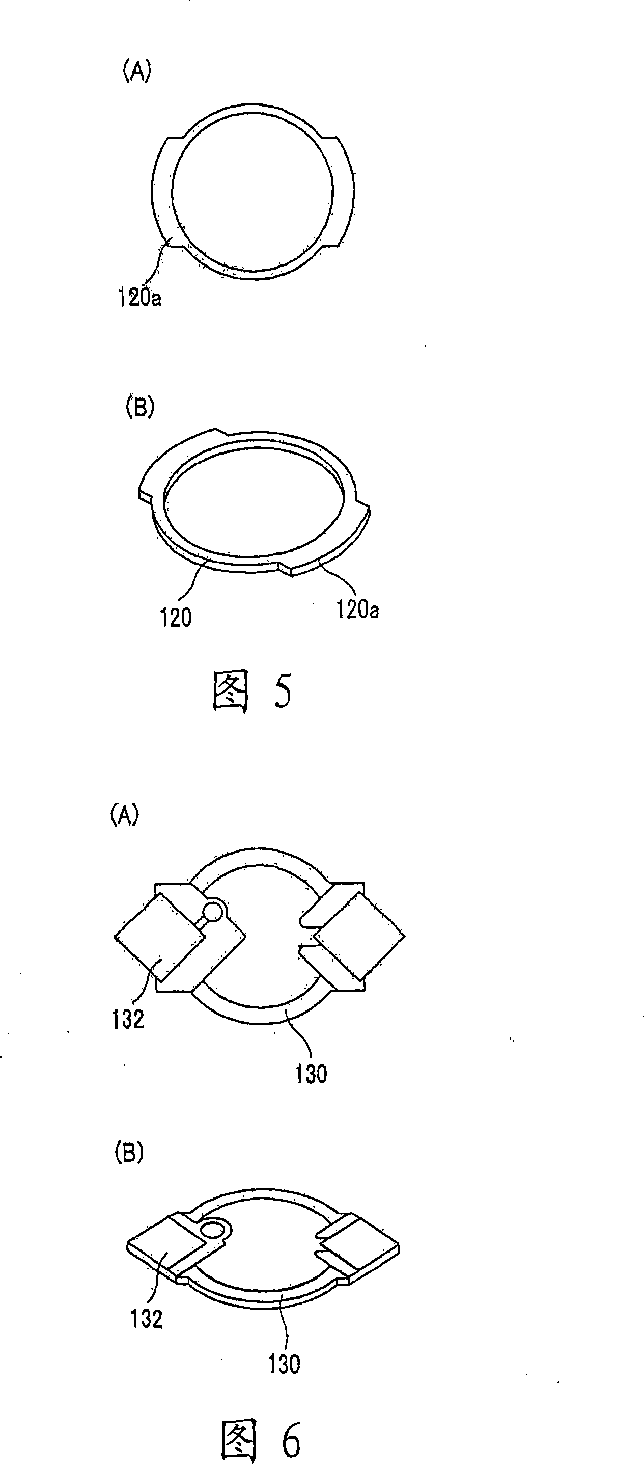
[0042] As shown in FIG. 7, the method of manufacturing a condenser microphone using the above-mentioned main components according to the first embodiment of the present invention includes: a step S11 of preparing a casing 110; a step S12 of attaching a gasket 120 to the groove 110a of the casing ; a step S13 of inserting the internal components into the case 110; a step S14 of inserting the PCB 130; and a step S15 of crimping the protruding portion of the case.

[0043] Referring to FIG. 7, in step S11, the casing 110 having the groove 110a formed therein as shown in FIG. 4 is prepared, and in step S12, the gasket 120 shown in FIG. slot 110a. In step S13, such as a vibrating plate, a spacer, a first substrate, an electret backplane, and a second substrate are inserted into the housing 110, and in step S14 an integrated PCB with a tube 130a as shown in FIG. 130 is inserted into the housing 110 . The components inserted in step S13 may vary depending on the type of microphone....

no. 2 approach

[0048] 11 is a flowchart showing a manufacturing process of the condenser microphone according to the second embodiment of the present invention, and FIG. 12 is a diagram showing the condenser microphone according to the second embodiment of the present invention.

[0049] As shown in FIG. 11 , the manufacturing process of the condenser microphone according to the second embodiment of the present invention includes: a step S21 of preparing the casing 110; a step S22 of inserting internal components into the casing 110; Step S23 on the ring 140; step S24 of inserting the PCB 130; and step S25 of crimping the protruding portion of the case.

[0050] (A) and (B) of FIG. 12 are respectively a plan view and a side view showing a state where a gasket is stacked on an insulating ring, and (C) of FIG. 12 is a view showing a condenser microphone according to a second embodiment of the present invention. Side cutaway view. Referring to (C) of FIG. 12 , the vibrating plate 150 and the s...


PUM


Abstract

The present invention relates to a SMD type condenser microphone, and more particularly to a SMD condenser microphone and method for manufacturing the same wherein a sealing pad is employed to improve an acoustic characteristic. The SMD type condenser microphone to be mounted on a main PCB via an SMD process, the SMD type condenser microphone being assembled by inserting components and a PCB in a case comprises the case having an acoustic hole at a bottom surface thereof, the case including at least one groove on a sidewall thereof for exposing the PCB, wherein an extruding portion of the case is curled after the assembly; a ring type sealing pad wherein a portion thereof corresponding to the at least one groove is larger than a rest thereof so as to seal a coupling region when the case is coupled to the PCB; and the PCB having an inner portion inserted inside the case and a protruding portion extruding through the groove of the case.

Description

technical field [0001] The present invention relates to an SMD type condenser microphone, and more particularly to an SMD condenser microphone and a manufacturing method thereof, wherein a gasket is used to improve acoustic characteristics. Background technique [0002] With the development of electronic device manufacturing technology, the size of electronic devices tends to be reduced, and SMT (Surface Mount Technology) is widely used for small electronic devices. Especially, for small electronic devices such as cellular phones and PDAs, component mounting technology of SMD is more important. Therefore, most components used in cellular phones and the like are developed and used as parts for SMD with robust temperature characteristics, so that SMD technology can be employed. [0003] In general, since electret condenser microphones are manufactured by forcibly injecting electrons into organic membranes, charged electrons are easily separated at high humidity or high temper...

Claims


Application Information

Patent Timeline
IPC IPC(8): H04R19/04
CPCH04R19/04H04R31/00
Inventor 金锡镇李锺燮金昌元李源泽韩景九
Owner BSE CO LTD
Features
  • R&D
  • Intellectual Property
  • Life Sciences
  • Materials
  • Tech Scout
  • Unparalleled Data Quality
  • Higher Quality Content
  • 60% Fewer Hallucinations
Learn More