Clamping mechanism for double end threading machine

A technology of clamping mechanism and tapping machine, which is applied in the direction of clamping, thread cutting machine, metal processing machinery parts, etc., can solve the problems of difficult to achieve machining accuracy, poor safety, easy deviation, etc., and achieve quality and consistency assurance , Stable and safe work, stable and reliable operation

Inactive Publication Date: 2008-06-04
诸暨斯通机电设备制造有限公司
View PDF2 Cites 8 Cited by
  • Summary
  • Abstract
  • Description
  • Claims
  • Application Information

AI Technical Summary

Problems solved by technology

[0002] Thread processing involves all walks of life, but at present, most of the pipe fittings are tapped manually or semi-automatically, which has poor safety, low work efficiency, and high labor intensity. Difficult to achieve, and the processing equipment is bulky, the cost of consumables is high, the conditions for adapting to product specifications are poor, and maintenance is inconvenient
Especially the clamping mechanism in the tapping machine has a great influence on the tapping effect, and the existing clamping mechanism cannot be fully automated, and errors such as offset are prone to occur
Chinese patent 94211282.2 discloses a double-head tapping machine. The clamp is composed of a pair of clamp tires, and also includes a handle and a pull rod. This structure is beneficial to supply the workpiece in the chute to the clamp in time, but the clamping of the clamp The work efficiency is not high, and sometimes the accurate positioning of the workpiece is affected due to insufficient clamping force.
Although this mechanism can realize double stations, there are certain limitations, and the feeding cannot be automated, which affects the overall work efficiency and labor intensity.

Method used


Image

  • Clamping mechanism for double end threading machine
  • Clamping mechanism for double end threading machine
  • Clamping mechanism for double end threading machine

Examples


Embodiment 1

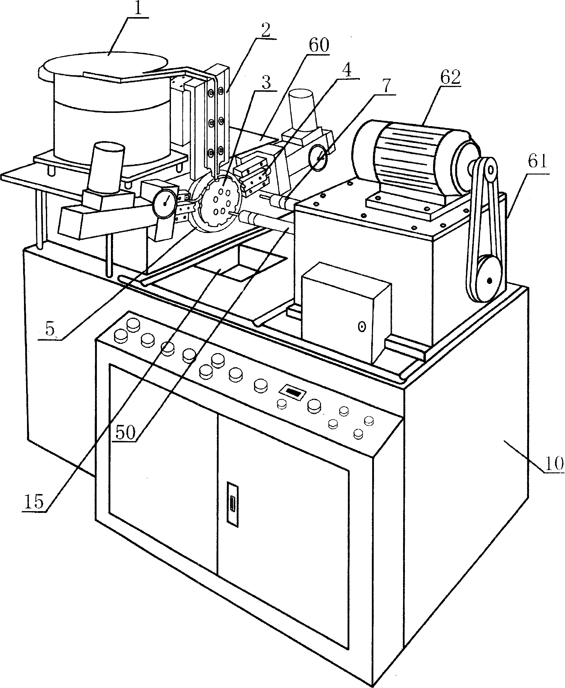
[0026] Embodiment 1: refer to attached figure 1 , the double-head tapping machine includes a fuselage (10), a vibrating feeding device (1) equipped with a workpiece (52) to be processed, a linear chute (2) for guiding materials, and is installed on a workbench (60). The workpiece clamping mechanism and the feed box (61) that control two tapping main shafts (50) horizontally feed, and the front end of the tapping main shaft (50) is provided with a tapping device (7). The clamping mechanism is installed on one side of the workbench (60), opposite to the feed box (61) and the motor (62) thereon, and the tapping on the tapping spindle (50) in the feed box (61) The device corresponds to the two processing positions on the chuck (3). The positioning mechanism is located at the rear of the chuck (3) and below the workbench (60).

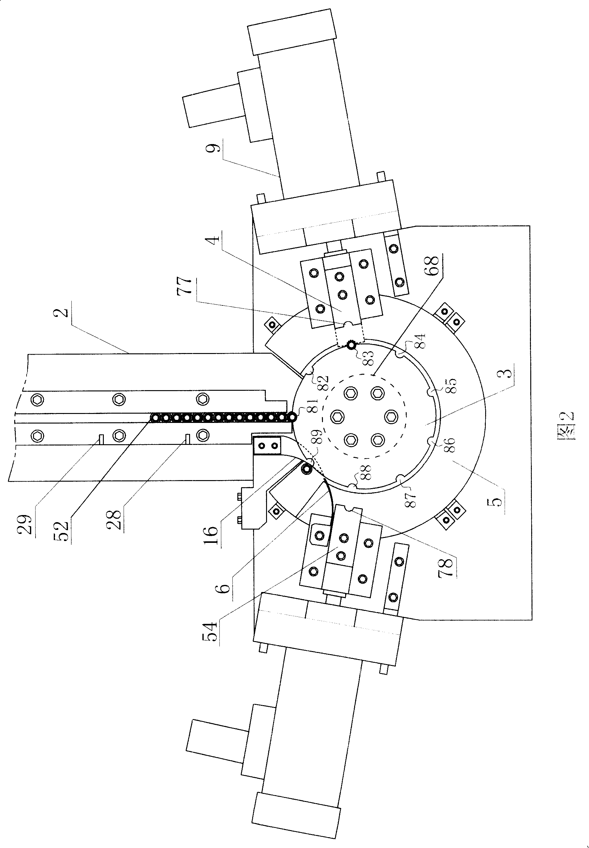
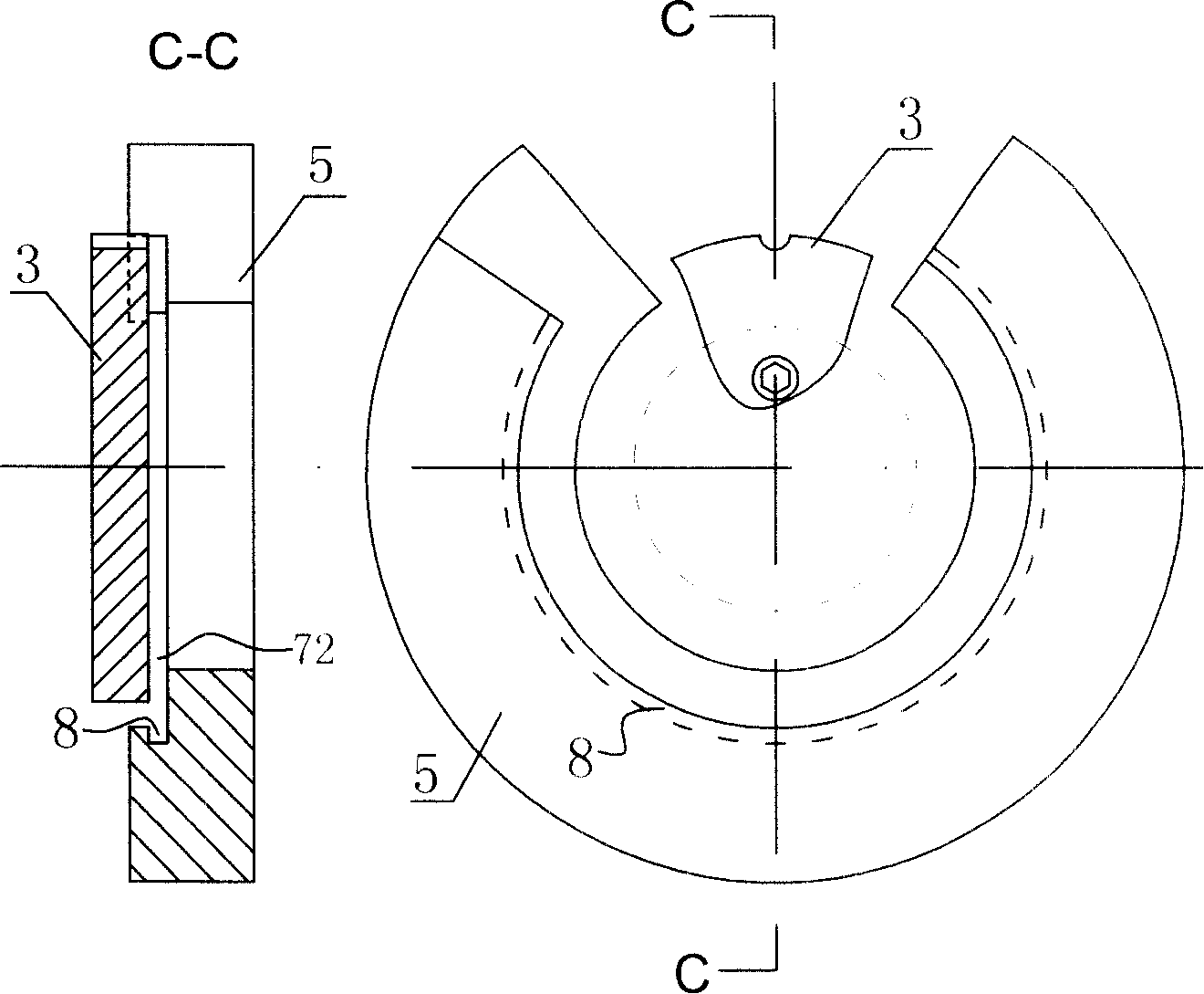
[0027] Refer to accompanying drawing 2, attached image 3 , the rotatable chuck (3) with a semi-circular arc clamping position is connected to the rotat...

Embodiment 2

[0034] Embodiment 2: The clamping positions on the chuck (3) are "V" type, and the number is 11, which are evenly arranged on its outer circumference. The opening grooves on the first clamp (4) and the second clamp (54) ( 77) is also a "V" type, corresponding to the card position. The angle that the chuck (3) rotates each time is 360°÷11×2. The included angles between the first clamp (4) and the second clamp (54) and the horizontal plane are 90°-(360°÷11×2), which are used to control the positioning wheel (11) in the positioning mechanism of the chuck (3) The number of cards on the card is also 11. Others can refer to embodiment 1, which is the same as embodiment 1.

[0035] The open groove (77) on the clamp among the present invention and the clamping position on the chuck (3) can have several different matching modes, as Figure 4 Shown: a, the clamping position on the chuck (3) is a semicircular arc groove, and the opening groove (77) is also a semicircular arc groove; b...


PUM


Abstract

The invention relates to a dual-head tapping machine holding mechanism, comprising a rotatable chuck with blocking position and clamps arranged at the two sides of the chuck; the external circumference of the chuck is provided with 9 blocking positions used for positioning workpiece; a guide chassis with internal troughs is arranged between a workbench and the chuck; the guide chassis is arranged in parallel with the chuck; the clamps are symmetrically arranged at the two sides of the chuck. The clamping head of the clamp is provided with an opening trough corresponding to the blocking position of the chuck. The rotation of the chuck is controlled by a positioning mechanism; a positioning wheel is coaxial with the chuck; the number of blocking positions on the position wheel is the same with that on the chuck. The invention is fully automatically controlled and has the advantages of high working efficiency, safely saving energy, wide processing range, and convenient maintenance.

Description

technical field [0001] The invention relates to a clamping mechanism for machining, in particular to a clamping mechanism for a double-head tapping machine. Background technique [0002] Thread processing involves all walks of life, but at present, most of the pipe fittings are tapped manually or semi-automatically, which has poor safety, low work efficiency, and high labor intensity. It is difficult to achieve, and the processing equipment is bulky, the cost of consumables is high, the conditions for adapting to product specifications are poor, and maintenance is inconvenient. In particular, the clamping mechanism in the tapping machine has a great influence on the tapping effect, and the existing clamping mechanism cannot be fully automated, and errors such as offset are prone to occur. Chinese patent 94211282.2 discloses a double-head tapping machine. The clamp is composed of a pair of clamp tires, and also includes a handle and a pull rod. This structure is beneficial t...

Claims


Application Information

Patent Timeline
Patent Type & Authority Applications(China)
IPC IPC(8): B23Q3/06B23Q16/02B23G1/20B23G1/22B23Q7/00B23Q7/08
Inventor 斯瑜彪
Owner 诸暨斯通机电设备制造有限公司
Why Eureka
Try Eureka