
Bottom wire-cutting device capable of adjusting length of cut suture line

A thread cutting and sewing technology, which is applied in the sewing machine to cut off the thread mechanism, sewing equipment, sewing machine components, etc. It can solve the problems of complicated procedures, affecting the appearance of the product, and the inability to adjust the cutter.

Inactive Publication Date: 2008-06-04
顾飞龙
View PDF0 Cites 6 Cited by
  • Summary
  • Abstract
  • Description
  • Claims
  • Application Information

AI Technical Summary

Problems solved by technology

[0005] 1. The cutting knife in the thread cutter (thread cutting device, lower knife device) cannot get closer to the sewing place to hook the suture for cutting action, so that the cut suture remaining on the workpiece has too long thread tail affect product appearance
[0006] 2. The cutting knives in the thread cutter (cutting device, lower knife device) cannot be adjusted so that the end of the cutting knife is close to the sewing thread, so that the length of the tail of the cut sewing thread left on the workpiece is reduced to improve the cutting speed. Appearance and texture of sewing workpiece products
[0007] 3. When the thread cutter (thread cutting device, lower cutter device) corresponds to the cloth pushing teeth (fourth and fifth teeth) with different numbers of teeth, in order to prevent the cutter from swinging at an angle, it will extend out the hook line in time and collide with the cloth pushing teeth Therefore, it is necessary to adjust the stroke distance of the thread cutter [cutting device, lower cutter device] to use accordingly, and the adjustment of the thread cutter [cutting device, lower cutter device] needs to be handled by a technician with a considerable technical background, and the procedures are complicated. Therefore, causing inconvenience in use

Method used

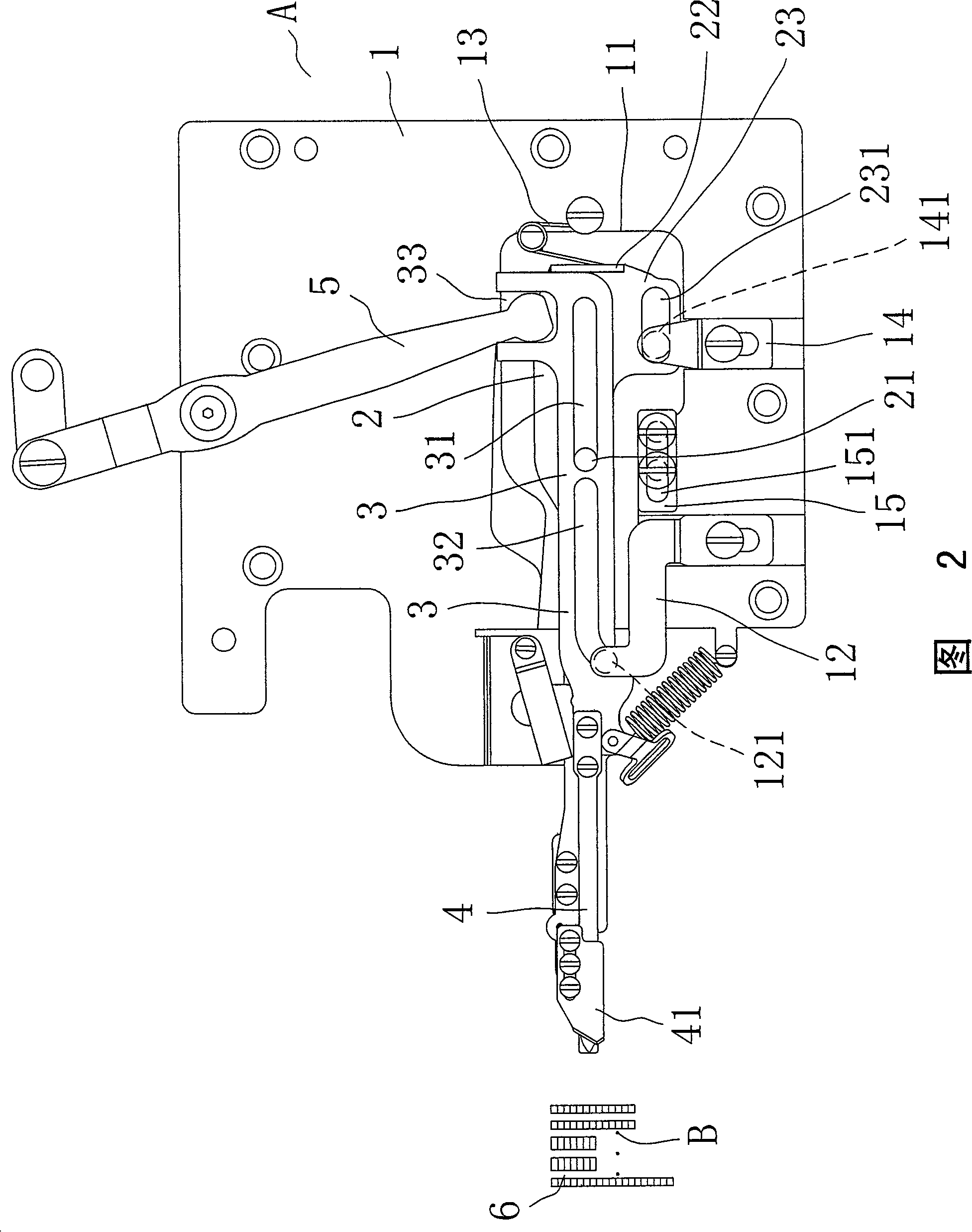
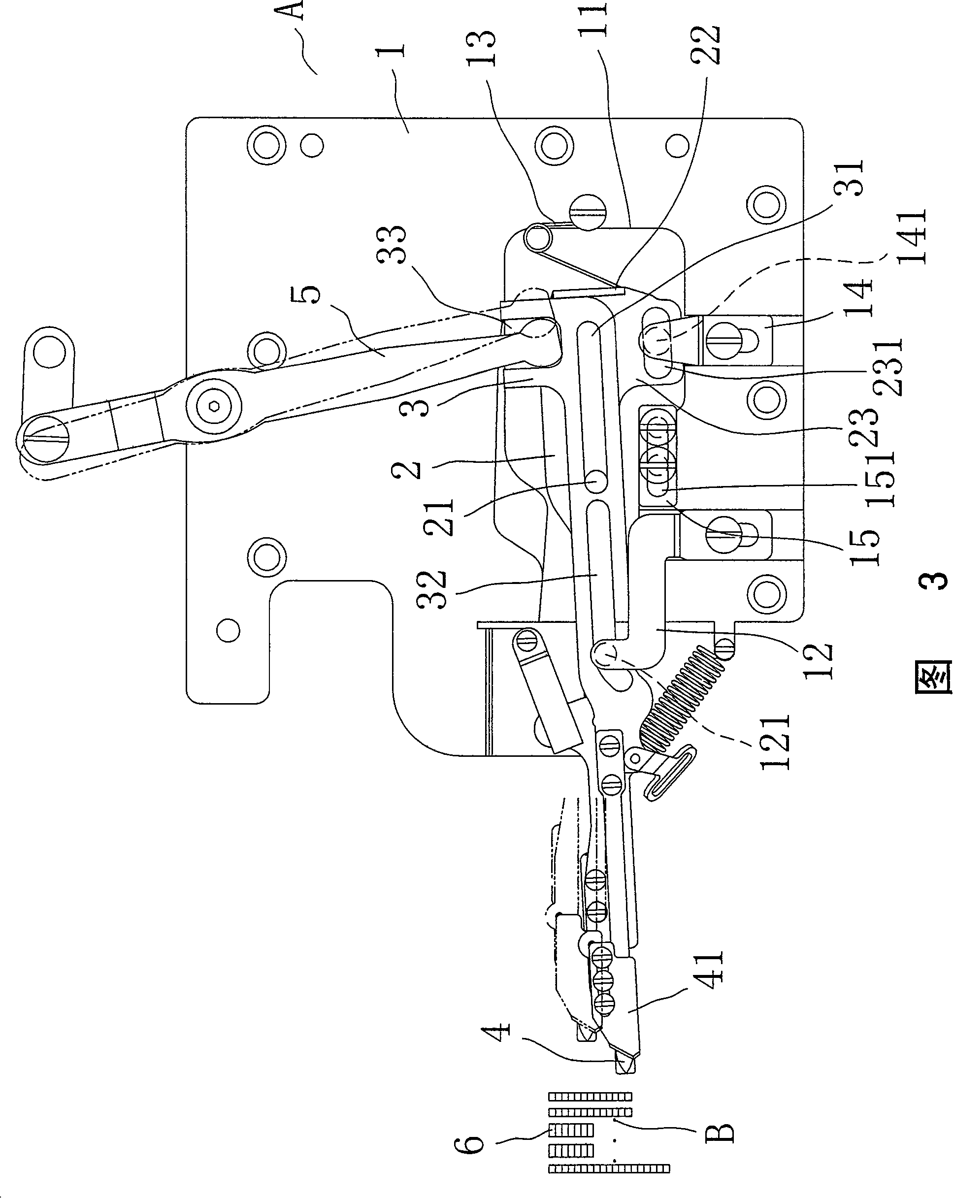

Image

  • Bottom wire-cutting device capable of adjusting length of cut suture line
  • Bottom wire-cutting device capable of adjusting length of cut suture line
  • Bottom wire-cutting device capable of adjusting length of cut suture line

Examples


Embodiment Construction

[0020] In order to understand more clearly the technical content of the present invention, the purpose of the invention and the effects it can achieve, the preferred embodiments of the present invention will be described in detail below with reference to the accompanying drawings:

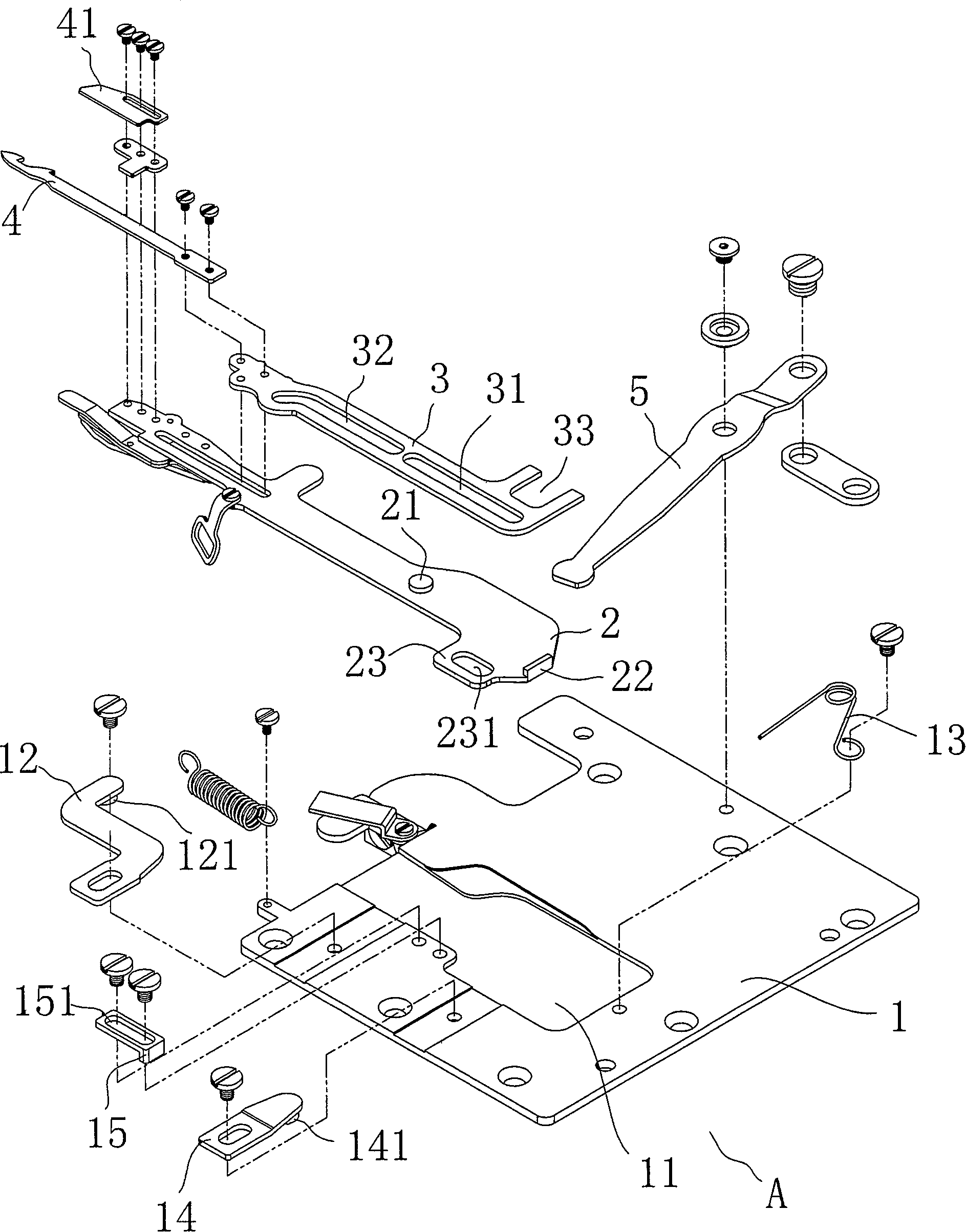
[0021] First, see figure 1 As shown, it is an overall exploded schematic view of the lower thread trimming device of the present invention that can adjust the length of the cut suture. The lower thread trimming device A is correspondingly assembled on the side of the needle suture. Correspondingly set a knife seat 2 in the groove 11, the front end of the knife seat 2 is provided with a blade 41, and a movable seat 3 with a guide groove 31 is correspondingly sleeved at the protrusion 21 of the knife seat 2, and the front end of the movable seat 3 is assembled with a Hook knife 4, the hook knife 4 can protrude from the blade 41 to hook the sewing thread, and then there is a turning groove 32 in front...


PUM


Abstract

The invention relates to a lower thread-cutting device capable of adjusting shearing stitch length, comprising a foundation plate and a correspondingly arranged tool post, wherein, cutting blades are arranged on the front end of the tool post; a sliding seat and a hooked knife are pivotally arranged on the tool post; a turning groove and a guide groove are arranged on the sliding seat and slide by being simultaneously driven by a locating rod which is arranged on the foundation plate, a convex grain nestion which is arranged on the tool post, and a swinging arm; the sliding seat and the hooked knife can slide and hook stitches; the cutting blades are used for shearing the stitches; a holding block and a convex plate provided with an adjusting groove are extended on the side of the tool post; the holding block is contradicted by an elastic holding piece which is fixed on the foundation plate; convex grains which are fixed on a limit rod of the foundation plate are correspondingly embedded into the adjusting groove on the convex plate; simultaneously, baffle plates capable of adjusting distance are arranged on the side of the foundation plate corresponding to the convex plate of the tool post. When the swinging arm drives the sliding seat and the hooked knife to advance, the tool post coordinates with holding advancement of the elastic holding piece through the adjusting groove of the convex plate being matched with the convex grains of the limit rod, and the whole tool post is made to move forward and then the cutting blades and the hooked knife are made to be closer to the stitches, thereby the motion of shearing lines is performed, consequently no ultra-long redundant stitch tails can be generated on workpieces.

Description

technical field [0001] The present invention relates to a lower thread trimmer that can adjust the length of the cut suture, especially a thread cutter that can slide the thread cutter for cutting the sewing thread to the sewing place near the needle, so as to cut out the shorter line segment remaining on the workpiece With the tangent structure, it achieves the above-mentioned implementation actions by means of the adjustment groove of the protruding piece that can move the knife seat forward and the design of the elastic resisting piece. Background technique [0002] Nowadays, all sewing machines have the function of automatic thread cutting, and the commonly seen thread cutter is provided with a driver on the sewing machine, and the driver can drive the thread cutting device. The thread cutting device includes: a base plate, which is fixed on the sewing machine , and the base plate has a sliding groove and a connecting groove not parallel to the direction of the sliding g...

Claims


Application Information

Patent Timeline
IPC IPC(8): D05B65/00D05B65/06
Inventor 顾飞龙
Owner 顾飞龙
Learn More