Machine tool with two clamp points on separate carriages

A clamping position, machine tool technology, applied in milling machines, milling machine equipment, manufacturing tools, etc., can solve problems such as unfavorable workpieces, workpiece accessibility limitations, and difficulty in achieving machine rigidity, etc., to improve machining accuracy and high machining accuracy. Effect

Inactive Publication Date: 2008-06-04
STARRAG
View PDF2 Cites 12 Cited by
  • Summary
  • Abstract
  • Description
  • Claims
  • Application Information

AI Technical Summary

Problems solved by technology

It is very difficult to achieve good machine rigidity with this scheme design of the machine tool described
Furthermore, although both slides of each workpiece holder are movable in the X direction, workpiece accessibility is limited
Especially if a second workpiece holder is provided, this situation is not conducive to contacting the workpiece during the processing of the workpiece

Method used


Image

  • Machine tool with two clamp points on separate carriages
  • Machine tool with two clamp points on separate carriages

Examples


Embodiment Construction

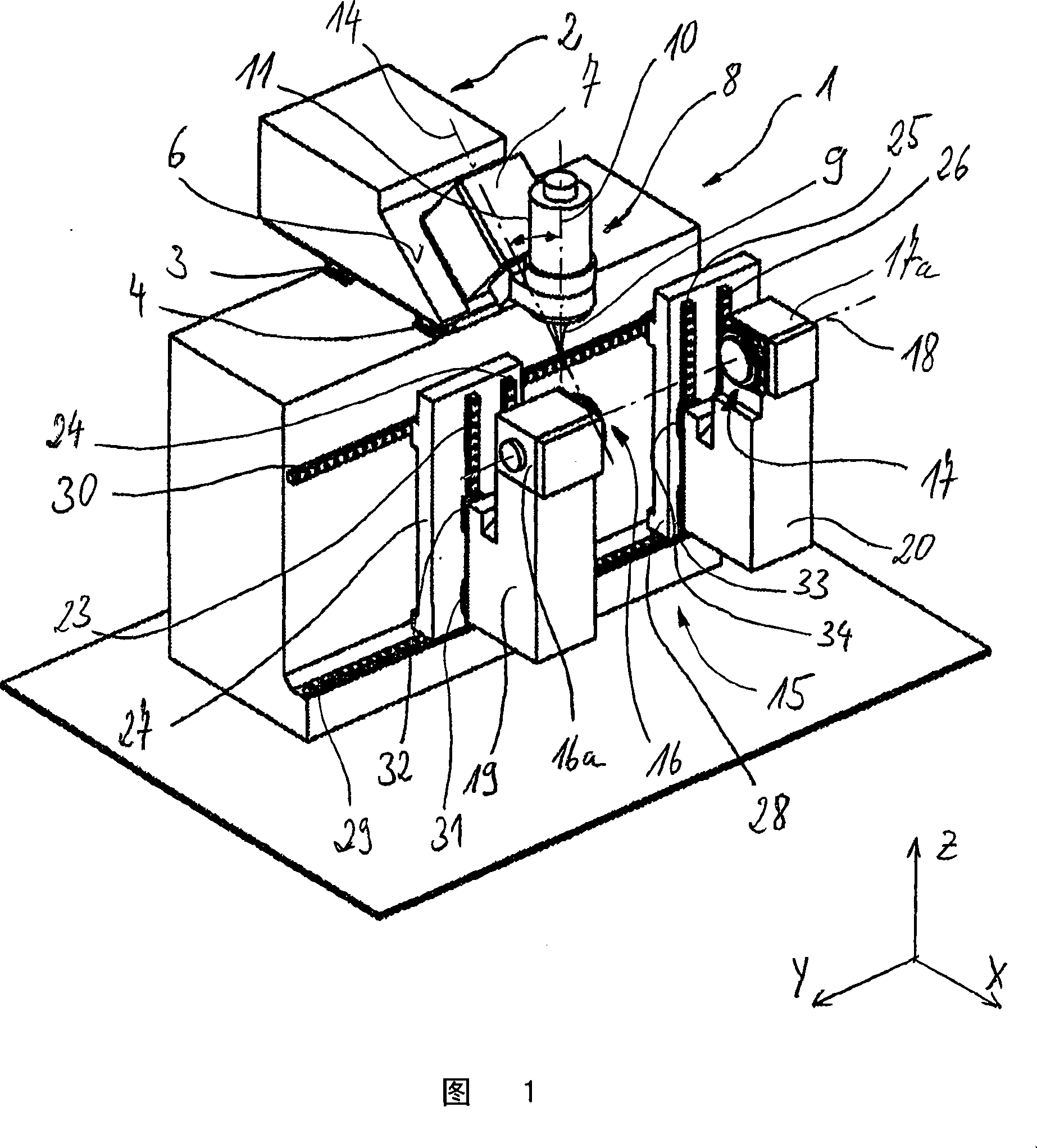
[0018] The machine tool shown very simply in FIG. 1 has a frame 1 on the upper side of which a first slide 2 is arranged. The slide 2 is movable in the X direction of the Cartesian coordinate system. The carriage 2 is displaceable via two linear displacement guides running parallel to one another, wherein a corresponding number of tool holder seats 3 , 4 are arranged on a linear displacement guide 5 . Only one of the guide rails 5 can be seen in the figure. In the tool carrier seats 3 , 4 on the linear movement guide, which has been mentioned several times before, the rolling bodies circulate in the circulation channel. In this case, the tool holders 3 , 4 are fixed on the frame 1 in a fixed position, while the guide rail 5 is mounted on the movable slide 2 .

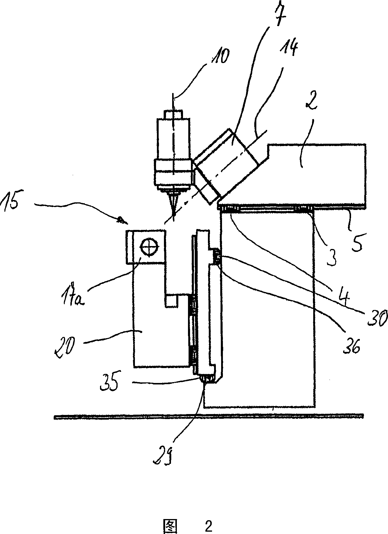
[0019] The slide 2 is provided with an inclined surface 6 on which a tool slide 7 is arranged. The tool slide 7 is displaceable on this surface 6 in the X-direction and in the Z-direction by means of two further line...


PUM


Abstract

The invention relates to a machine tool for milling workpieces, provided with at least two linear displacement axes and at least one pivot axis for carrying out relative movements between a tool and the corresponding workpiece with a workpiece mounting in which a workpiece may be clamped between two clamping points, whereby one of the linear displacement axes is provided as workpiece axis of the workpiece mounting, by means of which the workpiece may be linearly driven, which is furthermore provided with a tool holder for mounting a cutting machining tool, driven in rotation about a tool axis by means of a tool drive. The same conditions are achieved for workpieces of greatly different length for a highly accurate production, whereby two physically separate carriages (27, 28) for the workpiece mounting are provided, on each of which one of the clamping points (16, 17) is arranged and which both may be linearly driven along the same workpiece axis independently of each other.

Description

technical field [0001] The invention relates to a machine tool for milling workpieces, which is provided with a tool holder for holding a cutting tool and is also driven in rotation, and which has a workpiece holder in which , the workpiece can be clamped between two clamping positions, wherein the machine tool has a plurality of driven axes of motion, which are arranged for the machining of the machining tool on the workpiece, individually or in combination with each other The machining feed movement is generated as a relative movement of the machining tool relative to the workpiece, wherein the tool holder is provided with at least one linear movement axis of the driven movement axes, and the workpiece fixed seat is provided with There are at least two slides separated from each other on the body, on which one of the clamping positions is respectively arranged, the two slides of the workpiece holder can move together along at least one driven linear axis of movement move. ...

Claims


Application Information

Patent Timeline
Patent Type & Authority Applications(China)
IPC IPC(8): B23Q1/62B23Q39/02B23C3/18B23B23/00
CPCB23C1/06B23Q1/623B23Q1/54B23C3/18B23C2215/44Y10T29/5114Y10T409/303808Y10T409/305656Y10T409/307672B23B23/00B23Q1/62B23Q39/02
Inventor L·贝特肖恩C·格劳斯
Owner STARRAG
Why Eureka
Try Eureka