Mold and shaping technique for metal sheet material deep-drawing cup shell

A technology for sheet metal and cup-shaped parts, which is used in forming tools, metal processing equipment, manufacturing tools, etc., can solve the problems of poor drawing efficiency and quality of cup-shaped parts, uneven wall thickness distribution, deep drawing and forming. Failure and other problems, to achieve the effect of changing the metal flow trend, uniform wall thickness distribution, and delaying cracking

Inactive Publication Date: 2008-06-11
SHAANXI UNIV OF SCI & TECH
View PDF0 Cites 20 Cited by
  • Summary
  • Abstract
  • Description
  • Claims
  • Application Information

AI Technical Summary

Problems solved by technology

However, as far as the current technology and achievements are concerned, they are still at the stage of perceptual understanding. The determination and optimization of process parameters and mold structure often require long-term repeated experiments, which can be obtained by summarizing and inducing to improve the drawing efficiency and quality of cup-shaped parts. The effect is not obvious
Due to the uneven deformation and uneven wall thickness distribution of the cup-shaped parts during the deep-drawing process, the deep-drawing cracks always occur first at the place where the wall thickness is the largest and thinner, which leads to the failure of the entire deep-drawing forming, and the cracking defects The generation of the metal has a lot to do with the flow tendency of the metal during the deep drawing process

Method used


Image

  • Mold and shaping technique for metal sheet material deep-drawing cup shell

Examples


Embodiment Construction

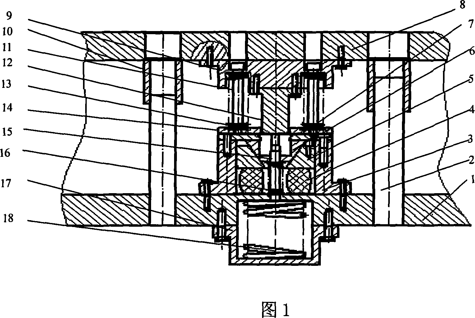
[0009] The present invention will be described in further detail below in conjunction with the accompanying drawings.

[0010] Referring to Fig. 1, it includes an upper mold base 8 and a lower mold base 1, the upper mold base 8 and the lower mold base 1 are connected through a guide post 2, and a guide sleeve 10 is also set on the guide post 2, and the upper die base 8 and the lower die base The base 1 is respectively provided with a corresponding punch 12 and a die 7, and the outside of the punch 12 is provided with a discharge screw 11 connected to the upper die base 8 and a blank holder spring 13 set on the discharge screw 11, The lower end of the discharge screw 11 is provided with a blank holder 14, the punch 12 and the discharge screw 11 are connected with the upper die base 8 through the upper die fixing block 9, and the outer side of the die 7 is provided with the lower die base 1. The fixedly connected container frame 3 is provided with a conical push block 5 and a ru...


PUM


Abstract

The invention discloses a die assembly of metal plate deep-drawing cup shells and shaping process. The invention comprises an upper die holder and a lower die holder, wherein a punch and a cavity die which are mutually corresponded are respectively arranged on the upper die holder and the lower die holder, a discharging screw which is connected with the upper die holder and a flanging spring which is sleeved on the discharging screw are arranged on the outer side of the punch, a blank holder is arranged on the lower end of the discharging screw, a holding frame which is fixedly connected with the lower die holder is arranged on the outer side of the cavity die, a conical pushing block and a rubber pad are arranged in turn in the holding frame from top to bottom, a conical enclasping element which is matched with the punch is arranged in the conical pushing block, a spring holder is arranged on the lower end of the lower die holder, a material squeezing spring is arranged in the spring holder, and a push rod which is extended through the rubber pat, the conical pushing block, and a conical clamping element is arranged on the upper end of the material squeezing spring. The invention carries out enclasping along the side-wall direction during the deep-drawing process of cup shells, material flowing tendency can be changed flexibly and actively, which enables wall thickness to be changed evenly, maximum thinning-out quantity on a dangerous cross portion during the process for drawing can be minimized and drawing breakage can be avoided.

Description

technical field [0001] The invention belongs to the field of material forming and moulds, and in particular relates to a mold and a forming process for a sheet metal drawing cup-shaped part. Background technique [0002] Sheet metal stamping has been widely used in many fields. How to make full use of the forming properties of materials, discover new forming processes and methods, and improve forming efficiency and quality is an important topic facing the entire industry, and it is also a hot research topic in plastic processing circles at home and abroad. Cup-shaped deep drawing is the most widely used forming process in the field of sheet metal stamping and forming. Deep forming efficiency and quality, especially the research on blank holder force, punch fillet, die fillet, lubrication conditions and other process parameters and die structure. However, as far as the current technology and achievements are concerned, they are still at the stage of perceptual understanding...

Claims


Application Information

Patent Timeline
Patent Type & Authority Applications(China)
IPC IPC(8): B21D37/10B21D37/12B21D22/20
Inventor 杨立军党新安张昌松
Owner SHAANXI UNIV OF SCI & TECH
Why Eureka
Try Eureka