Ultrasound wave auxiliary laser braze (fuse) welding method

An auxiliary laser and ultrasonic welding technology, applied in laser welding equipment, welding equipment, welding equipment and other directions, can solve the problems of insufficient filling amount, insufficient solder penetration, poor wetting and spreading, etc., to reduce laser power and increase welding. Seam filling, improving the effect of weld formation

Inactive Publication Date: 2008-06-11
HARBIN INST OF TECH
View PDF0 Cites 53 Cited by
  • Summary
  • Abstract
  • Description
  • Claims
  • Application Information

AI Technical Summary

Problems solved by technology

[0004] The purpose of the present invention is to solve the problems such as poor wettability and spreadability, insufficient filling amount, pores and incomplete penetration of solder in the process o

Method used


Image

  • Ultrasound wave auxiliary laser braze (fuse) welding method
  • Ultrasound wave auxiliary laser braze (fuse) welding method

Examples


Example Embodiment

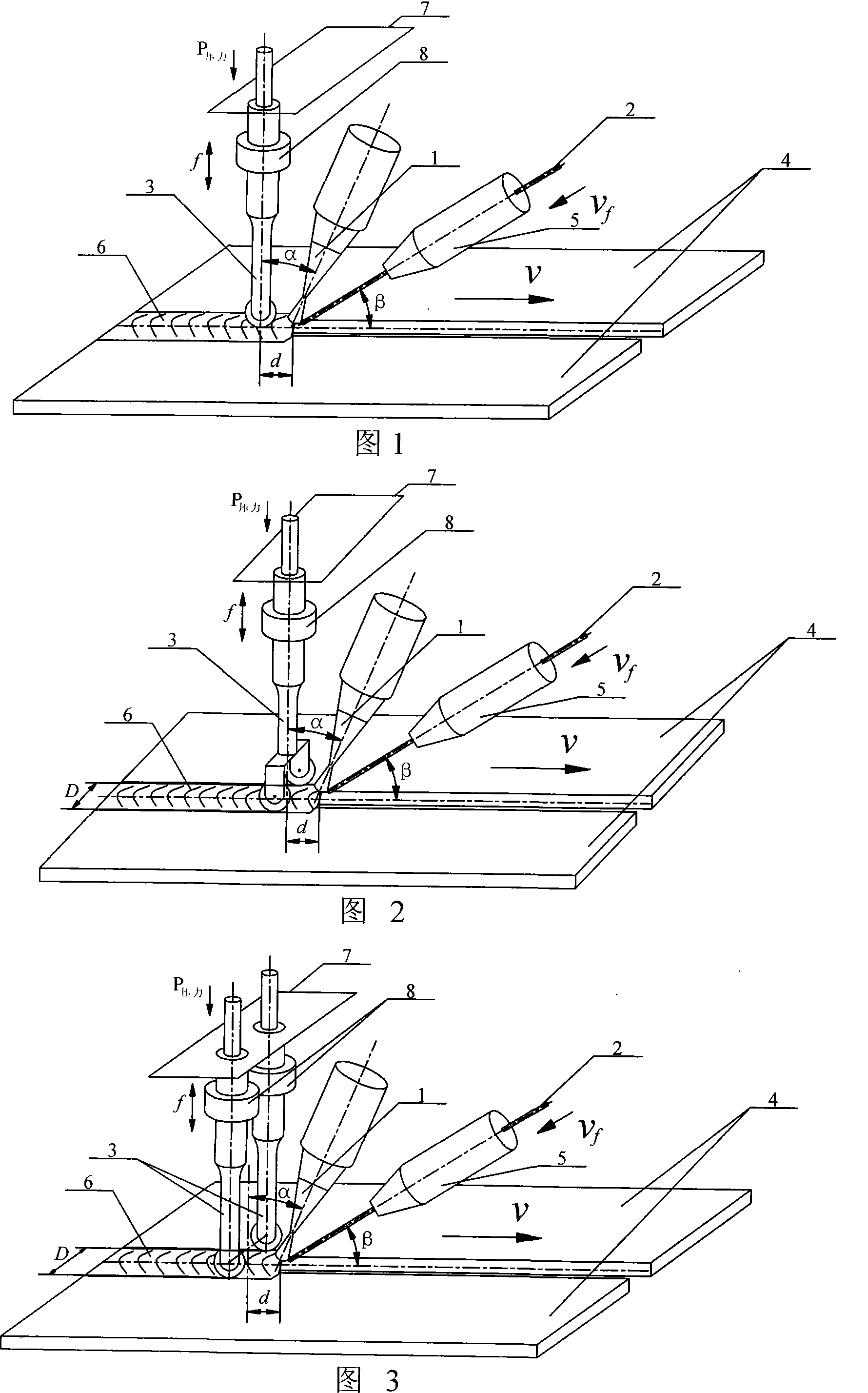
[0012] Specific embodiment one: (see Figure 1, Figure 2 and Figure 3) The ultrasonic-assisted laser brazing (melting) welding method of this embodiment is to weld low-melting-point coating metals or dissimilar metals by a combination of ultrasonic and laser brazing (melting) welding processes Material, that is, in the process of using laser brazing low melting point coating metal or laser brazing to weld dissimilar metals, high-frequency vibrating ultrasonic waves are applied in the weld area to be solidified at the same time. Ultrasonic waves are generated by ultrasonic welding equipment. Ultrasonic welding equipment Acting vertically above the weld area, its working pressure P 压力 It is 0.1~0.5MPa and the working frequency is 20~100kHz. The laser is directly irradiated on the workpiece and the welding wire in a defocused form. The energy ratio acting on the welding wire and the workpiece is 1.2~1.3:1, and the laser spot diameter is 2 ~5mm, the angle a between the laser and the ul...

Example Embodiment

[0014] The second embodiment: The difference between this embodiment and the first embodiment is that the laser is made of CO 2 Gas laser, YAG solid-state laser or semiconductor laser output. Others are the same as the first embodiment.

Example Embodiment

[0015] Specific embodiment three: (see Figure 1) This embodiment is different from specific embodiment one in that the horn of the ultrasonic welding device is aligned with the laser and welding wire to act in the middle of the weld, between the ultrasonic horn and the laser incident position The distance d is 3 to 6 mm. Others are the same as the first embodiment.


PUM

PropertyMeasurementUnit
Diameteraaaaaaaaaa
Tensile strengthaaaaaaaaaa

Abstract

The invention discloses a method for brazing or fusion-welding through lasers with ultrasonic waves as auxiliaries, which relates to a welding method. The invention solves problems during processes that the lasers are used to braze or fusion-weld coating metals which has low melting points or dissimilar metals, and the problems are that wetting spreading property is bad, filling amount is not enough, stomatas and solders aren't welded fully and the like. The method of the invention is that during the processes that the lasers are used to braze the coating metals which has the low melting points or the lasers are used to fusion-weld the dissimilar metals, simultaneously, the ultrasonic waves with high-frequency vibrations are applied in welding zones which will be coagulated. The invention has the advantages that the occurrences of air holes can be minimized or avoided, and welding cost can be lowered. Welding solders can flow fully due to the high-frequency vibrations, which is beneficial for the wetting spreads of the welding solders and penetrations of the welding solders to the bottom portion of the welding zones, weld pool width and welding filling amount can be increased, the occurrences of welding defects as non-welding fully, undercuts and the like can be avoided, weld formations can be improved, and weld strength can be increased.

Description

technical field [0001] The invention belongs to the field of material processing engineering and relates to a welding method. Background technique [0002] As we all know, the high-quality and efficient connection of low-melting-point coated metals such as galvanized sheets, as well as dissimilar metals such as titanium and aluminum, aluminum and steel, copper and steel, has always been a technical problem in the field of welding. This is mainly because the welding of low-melting-point coating metals is prone to produce pores and low corrosion resistance of joints; for the connection of dissimilar materials, the difference in physical properties leads to large residual stress in the joints; in addition, the difference in crystallization chemical properties makes the weld extremely It is easy to form brittle and hard intermetallic compounds, both of which will reduce the performance of the joint. [0003] Compared with other heat source brazing (melting) welding and solid ph...

Claims


Application Information

Patent Timeline
IPC IPC(8): B23K1/005B23K26/42B23K103/18B23K26/70
Inventor 陈彦宾雷正龙叶广郁李俐群
Owner HARBIN INST OF TECH
Why Eureka
Try Eureka