
Laser enhancement device and electric arc welding system

A strengthening device and arc welding technology, applied in welding equipment, metal processing equipment, manufacturing tools, etc., can solve problems such as poor quality of welding products

Pending Publication Date: 2017-09-19
裴向东
View PDF6 Cites 1 Cited by
  • Summary
  • Abstract
  • Description
  • Claims
  • Application Information

AI Technical Summary

Problems solved by technology

It aims to improve the poor quality of welding products obtained by existing laser welding

Method used


Image

  • Laser enhancement device and electric arc welding system
  • Laser enhancement device and electric arc welding system
  • Laser enhancement device and electric arc welding system

Examples


Embodiment 1

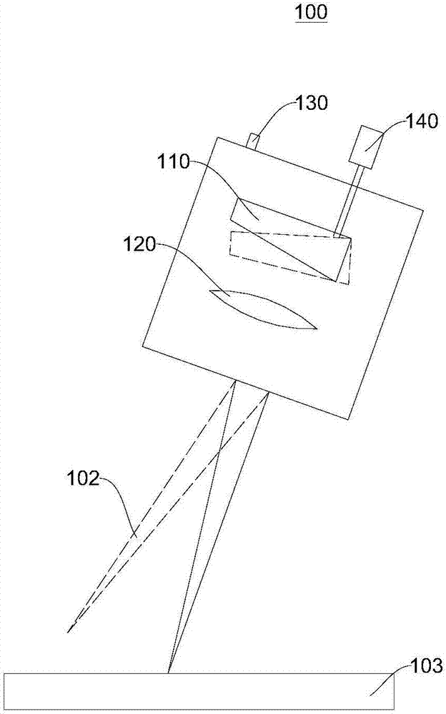
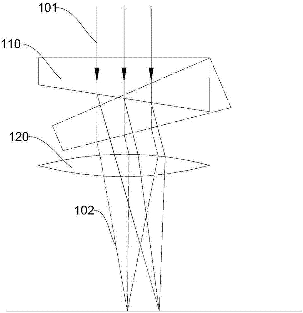
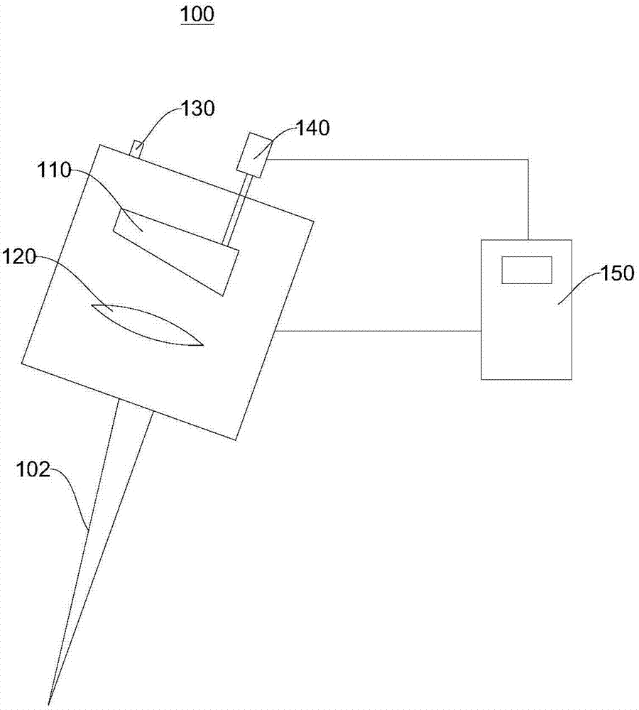
[0035] figure 1 For a schematic structural diagram of the laser intensifying device 100 provided in Embodiment 1 of the present invention, please refer to figure 1 . This embodiment provides a laser intensifying device 100. The laser intensifying device 100 includes an optical element 110, a focusing lens 120, an optical joint 130, and a driving device 140. The optical joint 130, the optical element 110, and the focusing lens 120 are used together. The laser 101 ( See figure 2 ) form the laser beam 102 through the optical joint 130, the optical element 110, and the focusing lens 120; the driving device 140 can drive the optical element 110 to rotate so that the laser beam 102 rotates along a preset track.

[0036] In this embodiment, the optical element 110, the focusing lens 120, and the optical joint 130 are all installed in the housing (not shown in the figure) of the laser intensifying device 100, and the optical element 110, the focusing lens 120, and the optical joint...

Embodiment 2

[0059] Figure 4 It is a schematic structural diagram of the arc welding system 200 provided in Embodiment 2 of the present invention, Figure 5 For a schematic diagram of the control principle of the arc welding system 200 provided in Embodiment 2 of the present invention, please refer to Figure 4 , Figure 5 , this embodiment provides an arc welding system 200, and the arc welding system 200 includes the laser intensifying device 100 of the first embodiment.

[0060] Further, the arc welding system 200 also includes a laser 210, a welding machine 230, and a welding torch 220. The welding machine 230 is used in conjunction with the welding torch 220. The laser 210 emits laser light 101, and the laser 210 is connected to the optical joint 130 of the laser intensifying device 100. The laser light 101 emitted by the laser 210 enters the laser intensifying device 100 through the optical joint 130 .

[0061] In this embodiment, the welding torch 220 has an included angle θ wit...


PUM


Abstract

The invention relates to the field of welding, in particular to a laser enhancement device and an electric arc welding system. The laser enhancement device comprises an optical element, a focusing lens, an optical connector and a driving unit. Laser light can sequentially pass through the optical connector, the optical element and the focusing lens to form a laser beam. The driving unit can drive the optical element to rotate so as to rotate the laser beam. The electric arc welding system comprises the laser enhancement device. The laser beam is driven by the driving unit to rotate along a preset path. Molten drops are transitioned at uniform sizes and frequencies. The laser beam heats the surface of a to-be-welded parent metal zone while cleaning the surface of the to-be-welded parent metal zone, so that the temperature of the surface of the to-be-welded parent metal zone is increased, the stability of the welding process is improved, and the welding quality is improved; and electric arcs are more stable by increasing the temperature of gas of the to-be-welded zone. The welding quality with the same fusion depth is achieved with low current, and low-spatter welding is achieved.

Description

technical field [0001] The invention relates to the field of welding, in particular to a laser intensifying device and an arc welding system. Background technique [0002] In the traditional arc processing technology, under the action of the arc, the stability of the droplet generated at the end of the welding wire directly determines the stability of the welding process. In the prior art, during the welding process, the droplet transfer is uneven, sometimes large particles transfer, sometimes short-circuit transfer, and the corresponding welding process is also unstable, which will inevitably cause serious welding spatter and welding defects, directly affecting the welding process. Quality of products. Contents of the invention [0003] The object of the present invention is to provide a laser intensifying device and an arc welding system. It aims to improve the problem of poor quality of welded products obtained by existing laser welding. [0004] The invention provid...

Claims


Application Information

Patent Timeline
IPC IPC(8): B23K28/02
CPCB23K28/02
Inventor 周立涛裴向东
Owner 裴向东
Learn More