A formwork component shaping mould

A mold shell component and molding mold technology, which is applied in molds, ceramic molding machines, mold separation devices, etc., can solve the problems of thin-walled boxes being easily damaged and inconvenient demoulding.

Inactive Publication Date: 2008-06-11
湖南邱则有专利战略策划有限公司
View PDF2 Cites 1 Cited by
  • Summary
  • Abstract
  • Description
  • Claims
  • Application Information

AI Technical Summary

Problems solved by technology

Such as the positive mold, as can be seen from their drawings, it includes a side mold surface and a lower mold surface (or a top mold surface), and the side mold surface and the lower mold surface form a male mold, which is the male mold of the overall template. In the actual use process, it is inconvenient to demould, and the open thin-walled tube or thin-walled box is easy to be damaged. Therefore, it is urgent to develop a new type of mold shell component forming mold.

Method used


Image

  • A formwork component shaping mould
  • A formwork component shaping mould
  • A formwork component shaping mould

Examples


Embodiment Construction

[0066] The present invention will be further described below with reference to the accompanying drawings and embodiments.

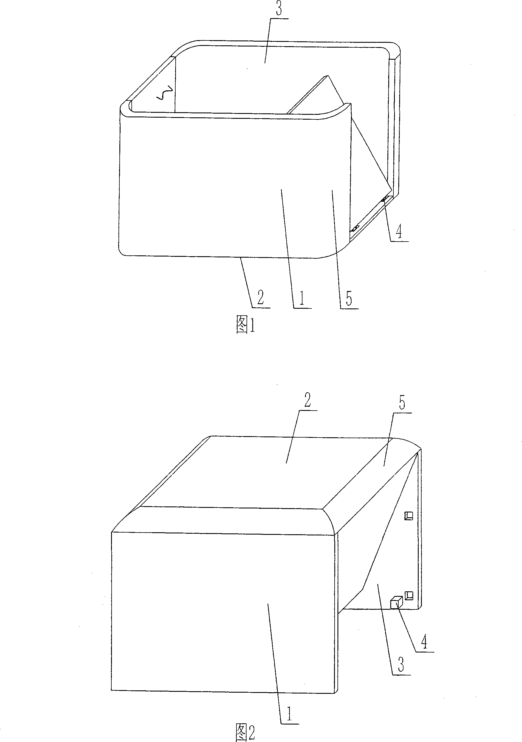
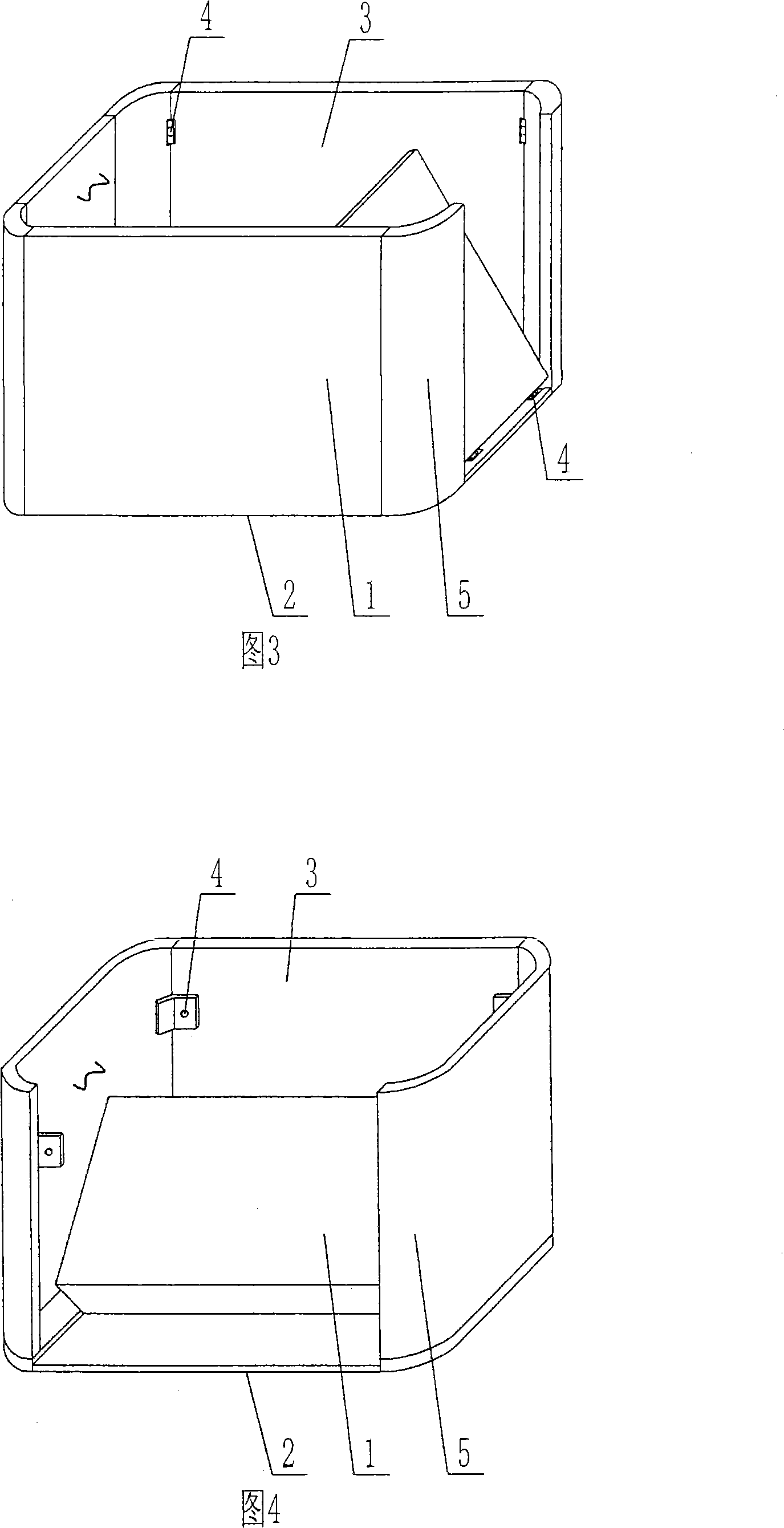
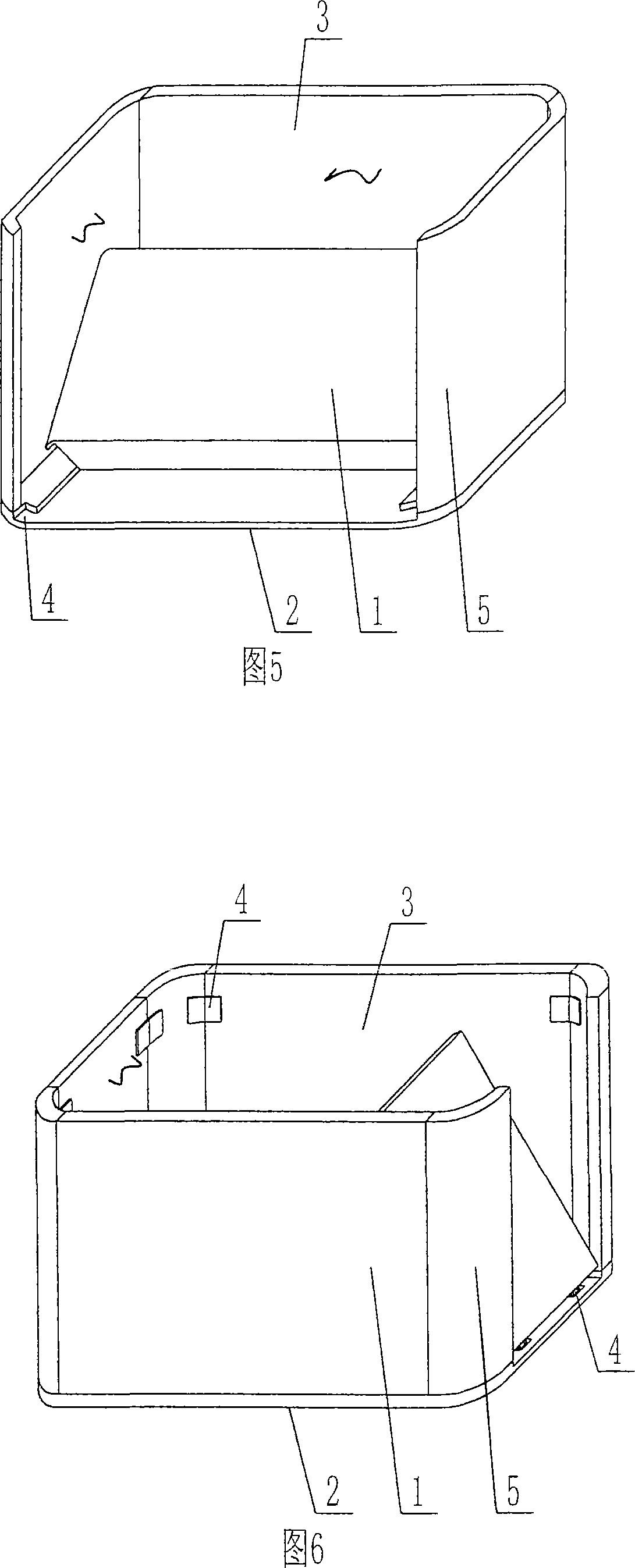
[0067] As shown in the accompanying drawings, the present invention includes a side die surface 1 and a lower die surface 2, and the side die surface 1 and the lower die surface 2 enclose a male die, which is characterized in that the side die surface 1 and the lower die surface of the male die are 2 is composed of a template 3, the male mold is composed of at least two templates 3 spliced ​​together, a splicing device 4 is provided on the assembled template 3, at least one corner part of the die surface is set as a curved or arc transition surface 5, and the side die surface 1 The corners between them are set as curved or arc transition surfaces 5 . FIG. 1 is a schematic structural diagram of Embodiment 1 of the present invention. In the drawings, 1 is the side die surface, 2 is the lower die surface, 3 is the template, 4 is the splicing device, and 5 i...


PUM


Abstract

Provided is a forming die of shuttering elements, which comprises a side form face (1) and a lower die face (2), wherein a male die is enclosed by the side form face (1) and the lower die face (2). The invention is characterized in that the side form face (1) and the lower die face (2) of the male die are composed of die plates (3), the male die is pieced together by at least two die plates (3), split units (4) are arranged on the pieced die plates (3), at least one corner portion of die surfaces is arranged as curve or arc transitional surface, and corner portions of side form face is designed as curve or arc transitional surfaces. After the shuttering elements are applied to cast-in-place concrete building floors, cantilever slabs can be taken as die plates of cast-in-place concrete ribs between the shuttering elements, thereby being capable of saving construction formworks, greatly improving construction speed and reducing construction costs. Furthermore, the invention achieves theend, which is adaptable for the application of cast-in-place reinforced concrete or prestressed reinforced concrete building floors, roofs, walls, foundation slabs and bridges.

Description

[0001] This application is a divisional application for an invention patent application with an application date of February 27, 2004, application number 200410005692.5, and titled "a mold for forming shell components". (1) Technical field [0002] The present invention relates to a mould for forming shell members. (2) Background technology [0003] At present, cast-in-situ reinforced concrete hollow slabs, especially cast-in-place reinforced concrete hollow slabs, are generally filled with thin-walled tubes or thin-walled boxes, which can meet the needs of various hollow slabs. On November 29, 1999, the applicant applied for an invention patent with an application number of 99115665.X, entitled "Fiber-reinforced thin-walled pipe (box) for reinforced concrete filling and its manufacturing method", and an application number of 99115666.8 , The invention patent titled "Fiber-reinforced thin-walled box for filling cast-in-place reinforced concrete and its manufacturing method",...

Claims


Application Information

Patent Timeline
Patent Type & Authority Applications(China)
IPC IPC(8): B28B7/22B28B7/16B28B7/34B28B7/26B28B7/04
Inventor 邱则有
Owner 湖南邱则有专利战略策划有限公司
Why Eureka
Try Eureka