Al technical title is built by PatSnap Al team. It summarizes the technical point description of the patent document.
A technology of lifting device and pile fixing frame, which is applied in water conservancy projects, artificial islands, underwater structures, etc., can solve the problems of long construction time, sudden broken teeth of gears or racks, and difficulty in inserting and pulling pins, so as to save marine life. Construction time and construction cost, good economic and social benefits, and the effect of improving safety and reliability
Inactive Publication Date: 2008-06-11
中石化石油工程技术服务有限公司 +1
View PDF0 Cites 28 Cited by
Summary
Abstract
Description
Claims
Application Information
AI Technical Summary
This helps you quickly interpret patents by identifying the three key elements:
Problems solved by technology
Method used
Benefits of technology
Problems solved by technology
The platform lifting device is the key part of the self-elevating platform, which is highly valued in the design and construction. The current lifting device generally adopts two forms: the cylinder jacking pin climbing rod type and the rack and pinion lifting device: the oil cylinder jacking pin climbing rod type The lifting device has disadvantages such as difficult insertion and removal of pins and difficulty in leveling the platform; the rack and pinion lifting device has the characteristics of continuous lifting, easy leveling, and convenient operation. It has many applications, but there are also many shortcomings, which are manifested in: The meshing of the strips is a line contact, the contact stress is large, and the load between multiple gears is unbalanced. The manufacturing process of the drive motor and the gearbox is complex and requires high precision. The existing materials and construction processes have reached their respective application limits. After this lifting system is used for a period of time, the gears and racks will be deformed to varying degrees, and the sudden tooth breakage of the gears or racks has occurred many times. Therefore, there are certain safety hazards.
And the above-mentioned lifting devices are all fixed on the platform, and a set of devices can only be applied to one platform
[0003] The current offshore fixed platforms are basically prefabricated in the shipyard first, and then completed by floating cranes, piling ships and other ships in the area where the platform is in place. Not only the offshore workload is heavy, the construction time is long, and the construction cost is expensive, but also Affected by the marine environment, it must be carried out in good weather, which will affect offshore production
Method used
Image
Click on the blue label to locate the original text in one second.
Reading with bidirectional positioning of images and text.
Examples
Embodiment Construction
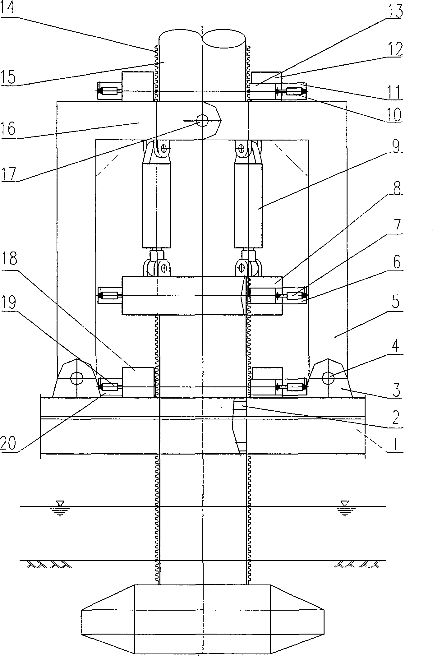
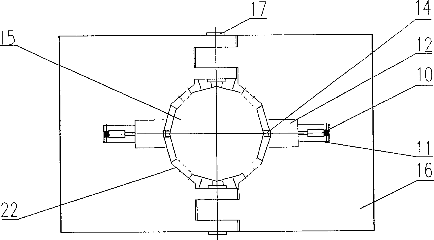
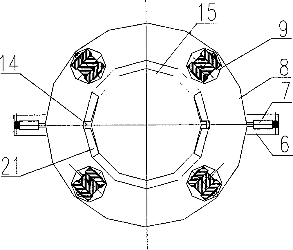
[0025] Now combined with the manual figure 1 , 2 , 3, the present invention is further described:
[0027] The function of the lifting device is to connect the platform with the legs to form a force transmission. There are three force transmission methods: (1), the platform body 1 is integrated with the movable pile fixing frame 5 through the platform connecting body ...
PUM
Abstract
The invention relates to a lifting device which can be reused. The device comprises a platform body, a guiding ring, a platform connecting body, a platform connecting pin, a movable pile fixing frame, a square beam, a ring beam push-pull cylinder bracket, a ring beam push-pull, a movable ring beam, a lifting cylinder, an upper row of push-pull cylinder, an upper row of push-pull cylinder bracket, an upper row of tooth block connecting body, a tooth block, a gear rack, a pile leg, a pile fixing frame connecting pin, a lower row of tooth block connecting body, a lower row of push-pull cylinder, a lower row of push-pull cylinder bracket, a ring beam guiding block and a pile fixing block. The force transmission and the relative movement between the platform body and the pile leg, and the lifting and the lowering of the platform are realized through the platform connecting body, the platform connecting pin, the movable pile fixing frame, the lifting cylinder, the ring beam, the square beam, the tooth block, and the gear rack. The tooth block and the gear rack are meshed through multiple teeth, the whole set of device is produced in a modularized way, and can be reused. The lifting device not only is secure and reliable, but also has low construction cost, thereby greatly saving the offshore construction expense time when be applied to a fixed platform.
Description
Technical field: [0001] The invention relates to a platform lifting system applied in ocean or lake operations. Background technique: [0002] With the exploration and development of marine resources, more and more offshore platforms are being built. Among them, in the shallow sea and even the middle and deep sea areas, the jack-up platform has the advantages of almost continuous work, stable operation and high efficiency in various sea conditions. It has been widely used and is the main platform in this sea area. The platform lifting device is the key part of the self-elevating platform, which is highly valued in the design and construction. The current lifting device generally adopts two forms: the cylinder jacking pin climbing rod type and the rack and pinion lifting device: the oil cylinder jacking pin climbing rod type The lifting device has disadvantages such as difficult insertion and removal of pins and difficulty in leveling the platform; the rack and pinion liftin...
Claims
Application Information
Patent Timeline
Application Date:The date an application was filed.
Publication Date:The date a patent or application was officially published.
First Publication Date:The earliest publication date of a patent with the same application number.
Issue Date:Publication date of the patent grant document.
PCT Entry Date:The Entry date of PCT National Phase.
Estimated Expiry Date:The statutory expiry date of a patent right according to the Patent Law, and it is the longest term of protection that the patent right can achieve without the termination of the patent right due to other reasons(Term extension factor has been taken into account ).
Invalid Date:Actual expiry date is based on effective date or publication date of legal transaction data of invalid patent.