
Assembled indoor stepless decorative wall

An assembled, decorative wall technology, applied in covering/lining, construction, building structure, etc., can solve the problems of noise, site cost loss, hindering new social needs, etc., to achieve the effect of easy installation and quick disassembly and assembly

Inactive Publication Date: 2008-06-11
王君
View PDF0 Cites 13 Cited by
  • Summary
  • Abstract
  • Description
  • Claims
  • Application Information

AI Technical Summary

Problems solved by technology

The main technical defect of the traditional interior decoration technology is: in each installation procedure, it is necessary to carry out destructive construction on the wall (including the ground and the roof) of the building. The result of this construction is to generate noise, dust, etc. and smell and a lot of garbage
resulting in large operating losses
The replacement of the office decoration in the commercial building will also hinder the operation of the original enterprise, and even have to stop some work
For newly moved companies, the complicated decoration process will have a negative impact on the opening time of the company, and will also cause a corresponding loss of site costs
[0006] To sum up, the traditional interior wall decoration technology has seriously hindered the realization of the new social demands put forward by people in modern society for decoration.

Method used


Image

  • Assembled indoor stepless decorative wall
  • Assembled indoor stepless decorative wall
  • Assembled indoor stepless decorative wall

Examples


Embodiment 1

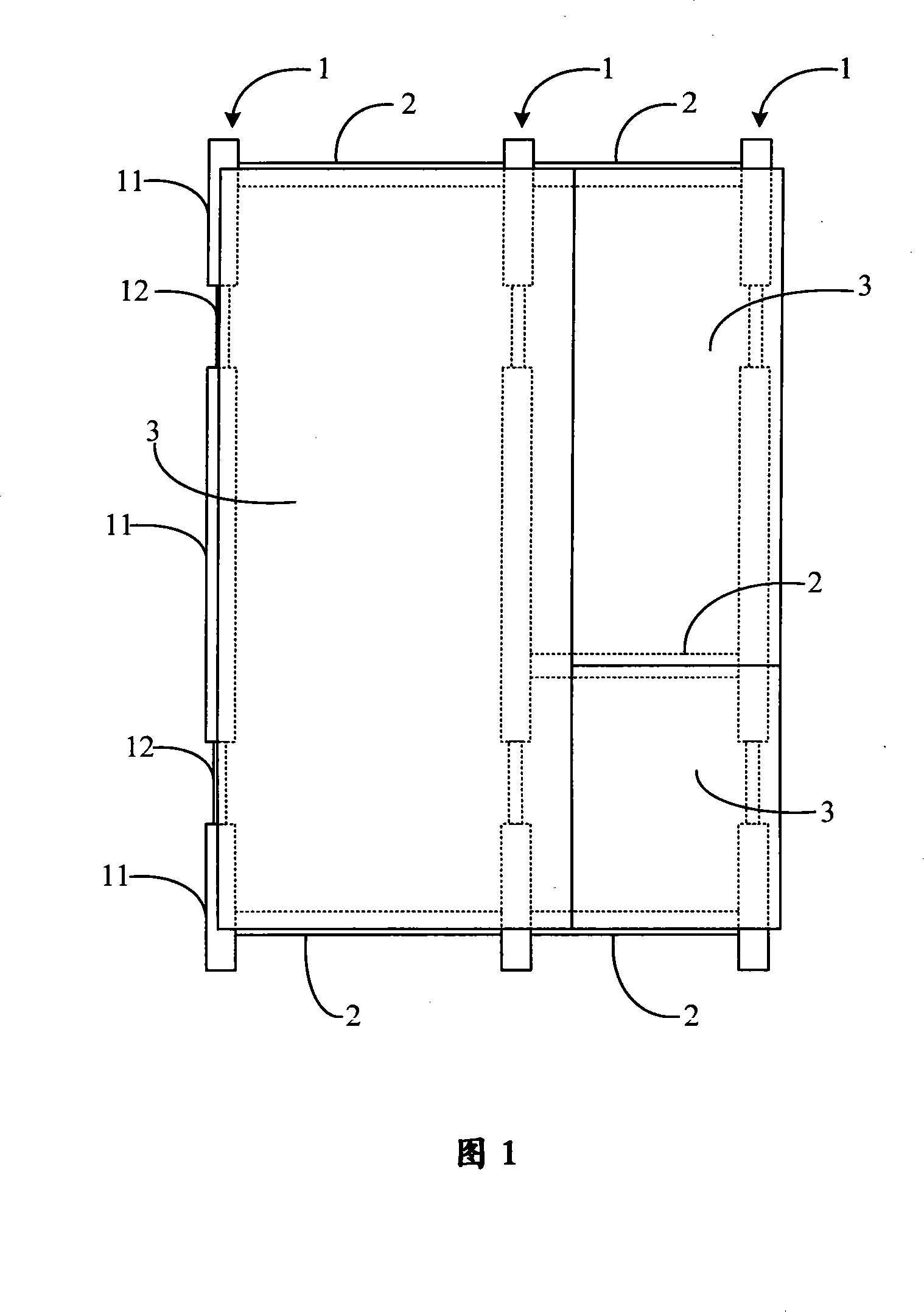
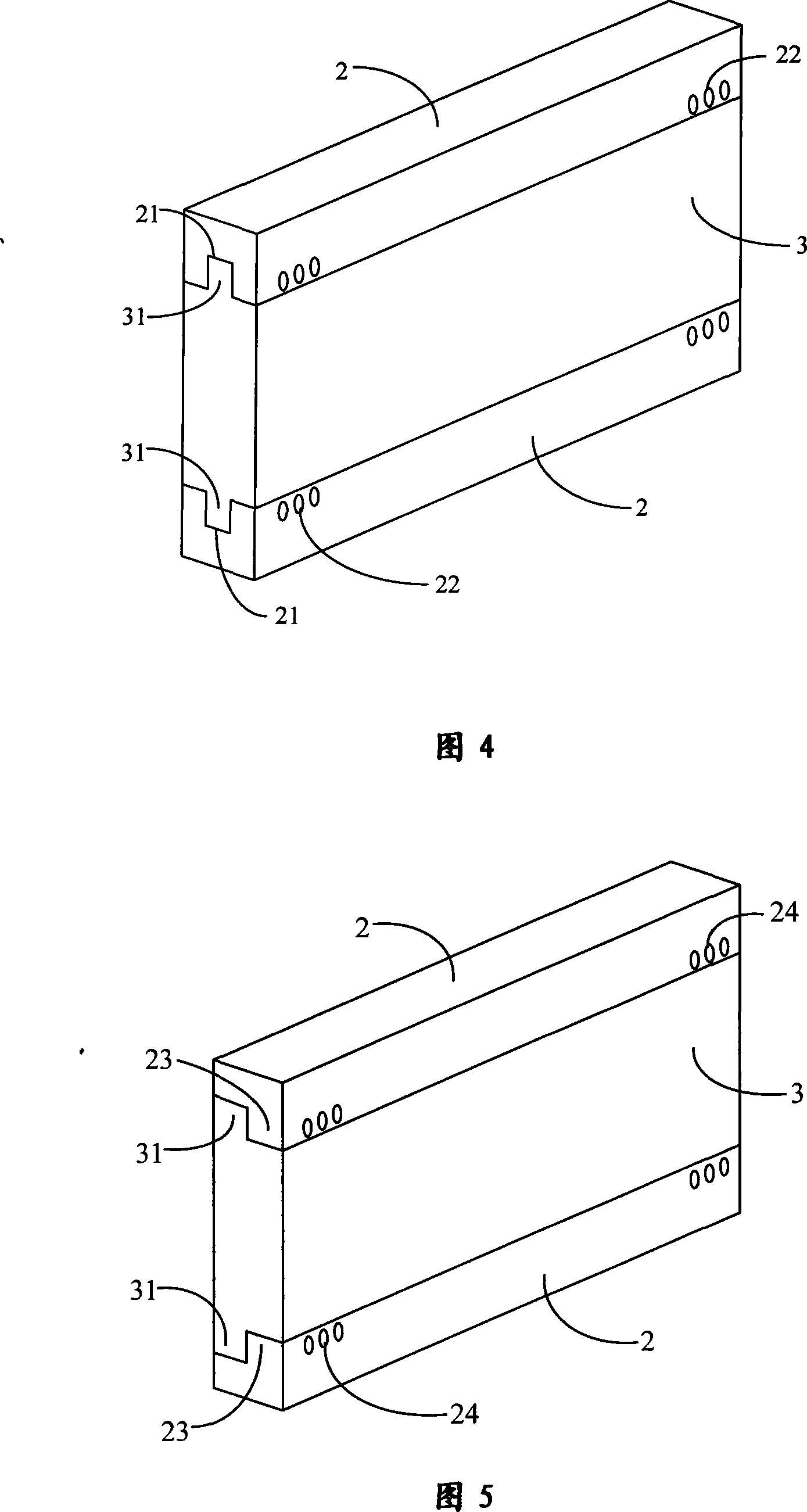
[0052] Figure 1 shows the basic structure of an indoor stepless decorative wall panel of the present invention, including a support body composed of three longitudinal pillars 1 and five transverse connecting rods 2 connected between the longitudinal pillars 1 . Three wall panels 3 of different sizes are installed on the support body. The longitudinal strut 1 is composed of three longitudinal unit columns 11 telescopically connected end-to-end through longitudinal connecting parts 12 . The transverse connecting rod 2 is provided with a receiving part, and the upper and lower ends of the wallboard 3 are respectively provided with mounting parts matching the receiving part. The wallboard 3 is installed on the support body through the mating connection between its installation part and the receiving part.

[0053] The connection structure between the longitudinal unit columns 11 is shown in FIG. 2 . The longitudinal unit column 11 is a column body with screw holes on the end su...

Embodiment 2

[0062] As shown in Figure 6, the difference between this embodiment and the above-mentioned first embodiment is that the transverse connecting rod is similar to the longitudinal column in the first embodiment, and also consists of two (or multiple) transverse unit rods 25 through the transverse The connecting parts 26 are telescopically connected from head to tail. Through this telescopic connection to form a transverse link, the height and width of the entire support body can be adjusted together, which has better adaptability to the actual size of the site.

[0063] The structure and connection mode of the transverse unit bar 25 and the transverse connecting member 26 can be completely the same as or similar to that of the longitudinal column, and will not be repeated here.

[0064]In addition, in the above two embodiments, the receiving portion provided on the transverse connecting rod, the mounting portion provided at the upper and lower ends of the wallboard, and the matc...

Embodiment 3

[0080] Fig. 21 is a partial structural schematic diagram of the third embodiment of the present invention. The difference between this embodiment and the above-mentioned embodiment is that: the surface of the gap between the upper wallboard B and the lower wallboard C is buckled with a transverse lath D, and the gap between two adjacent wallboards on the same floor The surface of the slot is buckled with longitudinal slats E.

[0081] After the overall structure of the indoor stepless decorative wall is installed, it is often necessary to install pipelines in the gaps between the wall panels, and when the transverse connecting rod is fixedly connected to the installation part of the wall panel through the receiving part, it is usually exposed Bolts and other installation parts make the wall unattractive. Moreover, because there are gaps between the wall panels, the decorative wall has the defects of ventilation, sound insulation and incompleteness. Thus, a complete closure ca...


PUM


Abstract

The invention relates to a consolidating type indoor stepless decorative wall, which comprises a supporting frame composed of a plurality of longitudinal supporting columns and a plurality of transversal connecting rods connectedly arranged between the longitudinal supporting columns and a wall plate installed and arranged on the supporting frame, wherein, and the longitudinal supporting columns are composed of a plurality of longitudinal unit columns through the head to trail telescopic connection of the longitudinal connecting parts; taking-up parts used for being connected with the wall plate are arranged on the transversal connecting rods; installing parts used for being matched and connected with the taking-up parts are arranged at the upper end and the lower end of the wall plate. The invention provides a complete and brand-new indoor wall decorating mode, any construction to the wall is not required at site, the proper modularization parts can be conveniently chosen at site to form the decorating wall, thereby ensuring the users to conveniently adjust the indoor environment according to own interest, the defect existing in the traditional indoor wall decoration is overcome, and the various requests to the indoor wall decoration brought forward by the modern society is fully satisfied.

Description

technical field [0001] The invention relates to an assembled indoor stepless decorative wall, in particular to an indoor stepless decorative wall which adopts standard modular components and can be quickly and flexibly assembled and installed on the decoration site according to the actual size, and does not need to carry out civil engineering construction on the building. level decorative wall. Background technique [0002] The current interior decoration is affected by traditional decoration techniques and crafts, and a large amount of civil engineering construction needs to be carried out on the building itself, which not only requires a long renovation period, but also produces garbage, noise, dust, etc. The impact on the surrounding environment And destruction has produced larger social problems. [0003] In the treatment of the wall surface, the traditional decoration technology usually first drills holes on the indoor wall to install expansion bolts or wooden plugs wi...

Claims


Application Information

Patent Timeline
IPC IPC(8): E04F13/08
Inventor 王君
Owner 王君
Learn More